
Filters
Choose your product
Exxelia offers a wide range of EMI-RFI and EMC filters.
Exxelia combines its expertise in capacitors and magnetic components to develop EMI-RFI low pass filters as well as EMC (TEMPEST, IEMN) filters.
RoHS
compliant versions
35
MIL
qualifications
50
ESA
QPL or EPPL series
Highlighted products

Frequently Asked Questions
A three-section filter consisting of two series-connected inductors between the input and output terminals, with a feedthrough capacitor between them from line to ground. The T filter is usually symmetrical (identical inductive elements), but circumstances sometimes warrant use of asymmetrical circuits. A T filter has attenuation characteristics that increase at 60 dB from its cutoff frequency to at least that frequency where it exhibits a minimum attenuation of 60 dB.
T-only filters are the choice when both the input and output impedances are low.
Two elements: a feedthrough capacitor from line to ground, and an inductor connected in series with it between the input and output terminals.
The capacitive element can be placed on either the line or load side of the filter, making it either a capacitive or inductive input. Its attenuation increases at 40 dB per decade from its cutoff frequency to at least that frequency where it exhibits a minimum attenuation of 70 dB. It maintains this level at higher frequencies. They are commonly referred to as L filters:
- L1 indicates that the inductive element is on the end with the threaded mounting neck.
- L2 indicates that the capacitive element is on the end with the threaded mounting neck. L-Only Filters or LL are used when the difference between line and load impedance is large.
The inductive element is best placed so that it faces the lower impedance.
It is built as a single element: a capacitor from line to ground, with a through wire connecting the input to output. It has attenuation characteristics that increase at 20 dB per decade from its cutoff frequency to at least that frequency where it exhibits a minimum attenuation of 60 dB. It maintains this attenuation at higher frequencies. A feedthrough capacitor filter is usually the best choice for filtering lines that exhibit very high impedance. A feedthrough capacitor, in this website, will be referred to as a C filter.
C-Only Filters are the choice for very high impedance lines.
A three-section filter consisting of two feedthrough capacitors to ground with a series inductor between them. The Pi filter is usually symmetrical, as are all the Pi filters in this catalog, but circumstances sometimes warrant use of asymmetrical Pi circuits. A Pi filter has attenuation characteristics that increase at 60 dB per decade from its cutoff frequency to at least that frequency where it exhibits a minimum attenuation of 80 dB. It maintains this level at higher frequencies.
Pi-Only Filters are the choice when high levels of attenuation are required and both the input & output impedances are similar.
Antiparasitic filters generally operate by impedance mismatch within a given frequency range.
The insertion loss of a filter in a supply or transmission circuit is defined as the ratio between the voltage values occuring at the line terminal leads immediately after the insertion point, before and after insertion.
Different standards specify the attenuation measurement possibilities in asymmetric (common mode) or symmetric (differential mode)
attenuation, measurements performed on load or no-load circuits.
The following standards are applicable :
- Standard GAM T 21
- Standard MIL STD 220 C
- Standard CISPR
The insertion loss performance is specified, measured according to the standard GAM T 21 or MIL STD 220 C in no-load conditions under an impedance of 50.
This measurement enables to check the compliance of the manufactured batch and to compare certain filters.
The real efficiency of a filter on an equipment can only be obtained by disturbance measurement taking into account the source and operating impedance.
For signal or data transmission filters usually defined in matched impedances, attenuation in the pass-band is measured according to the standard MIL 18327 E.
Yes, we have detailed specifications and we can share the qualification report.
Examples :
- for railway application : UNIFE & EN45545-2 compliance document.
- for space (from ESA) : 3201009/12, 3201011/12, 3201012/12
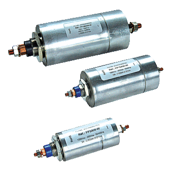
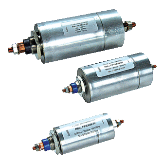
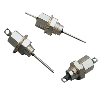
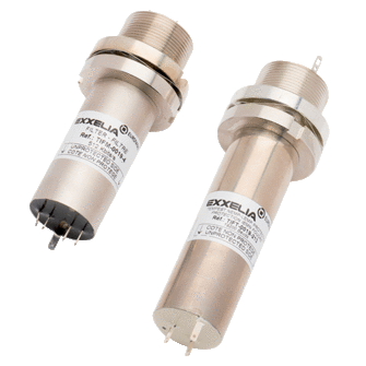
Many different kinds of filtering solutions are proposed such as C, L, Pi or T cells. Linked to the targeted performance, 14 specifications have been designed from diameter 30 to 100. Many variants are available to configure the internal components, the case plating (Gold, Steel), the threading, the sealing and the terminations.
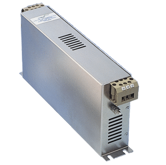
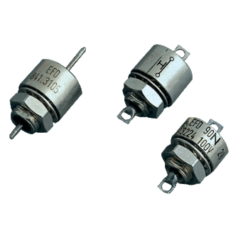
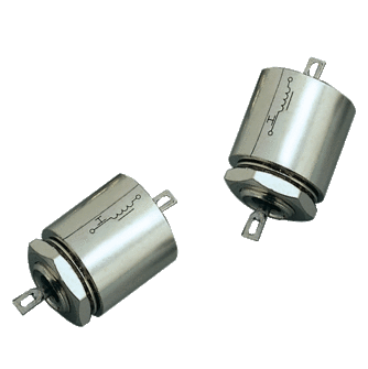
These products are created to be mounted on a PCB. They are clearly based on the same design than the tubular feedthrough filters with a shielded package. 4 specifications are proposed for Space applications (C, L, Pi or T cells with diameter 35 mm).
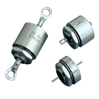
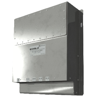
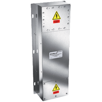
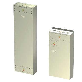
Exxelia added value is to reach any customer requirements owing to their mechanical division so that multiways feedthrough filters can be implemented to optimize installation and housing.
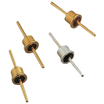
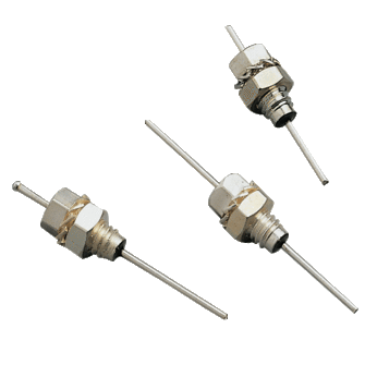
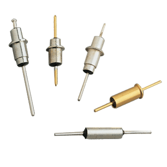
Exxelia manufactures miniature EMI filters based on ceramic capacitors and sometimes ferrite inductors in order to prevent disturbances generated by an appliance or to protect sensitive devices against those interferences.
Exxelia technologies’s filters are well known for their high reliability, robustness and electrical performances.
Moreover, they reach the ESCC requir ments and have been referenced in ESA EPPL for many years.
The function of an antiparasitic filter is to reduce the disturbance level to an admissible value to comply with the different standards or to reduce the sensitivity of an appliance within a given frequency range. For certain applications (HEMP - Lightning) protection against overvoltage is integrated into or added to the filter.
Antiparasitic filters are of the mismatched “Low-pass” type, except for special applications in telephone networks or in data transmission where they can be matched with impedance values of 50, 75, 100,120 or 600 Ohms in their band pass-range.
These filters operate by impedance mismatch in the frequency in which they are to provide their efficiency called “insertion loss”.
When selecting the structure of a filter, it is necessary to take into account the source and load impedance values, within the frequency range for which the disturbance level is to be reduced.
Still have questions ?


