
Exxelia High Voltage Pulse Capacitors – Key Takeaways
- Core Technologies & Capabilities: Exxelia manufactures high-voltage pulse capacitors across MLCC (Ceramic), Film / Film-Foil, and Tantalum technologies, engineered for low ESR/ESL, rapid charge/discharge cycles, and high energy density in harsh environments.
- Key Selection Criteria: Optimal pulse capacitor performance relies on precise matching of peak voltage, dV/dt slew rates, discharge current, operating temperature, and dielectric stability to prevent thermal stress and component degradation.
- High-Reliability Applications: Tailored for mission-critical functions in Aeronautics & Defense (radar, laser, fuzing systems), Space (satellite propulsion, power conversion), Medical (defibrillators, MRI), and Energy/Industrial applications.
- Exxelia Qualifications & Customization: Fully qualified under international space and military standards including ESA (ESCC QPL) and MIL-PRF / QPL, with custom packaging and high-reliability screening available for specific requirements.
Pulse Capacitors, in few words
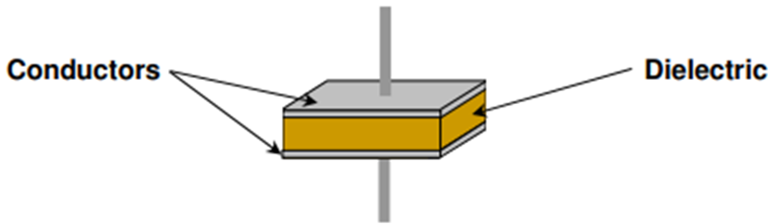
While conventional capacitors are designed to release energy gradually, pulse capacitors are highly specialized energy-storage devices engineered to charge relatively slowly and discharge extremely quickly. This rapid discharge allows them to deliver tremendous, short-duration high-current bursts, making them indispensable for systems operating under high electrical stress.
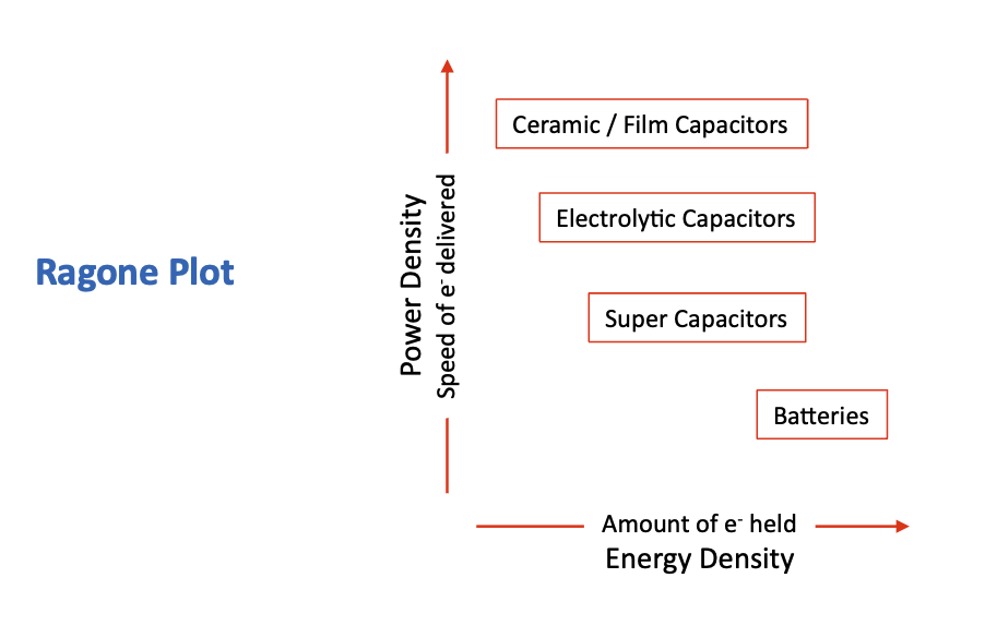
When comparing power sources for pulse applications, engineers often weigh capacitors against batteries. As illustrated by a standard Ragone plot, batteries are not typically considered for rapid pulse applications; capacitors offer a distinct advantage in terms of how fast the energy can be delivered.
Typical Applications
The demand for high voltage pulse capacitors is accelerating, primarily driven by the medical and military/defense sectors. Typical applications include:
- Military: Missiles, radar systems, high power microwave (HPM) for anti-drone systems, and fuzes/detonator capacitors.
- Medical: Advanced X-Ray equipment generation.
Capacitor Selection: The Ceramic advantage
When selecting a capacitor technology—typically deciding between ceramic, film, and electrolytic—ceramic and film capacitors exhibit far superior power density and response times. Furthermore, they outperform electrolytic options regarding loss characteristics, specifically Dissipation Factor (DF), Equivalent Series Resistance (ESR), and Equivalent Series Inductance (ESL).
When looking specifically at ceramics:
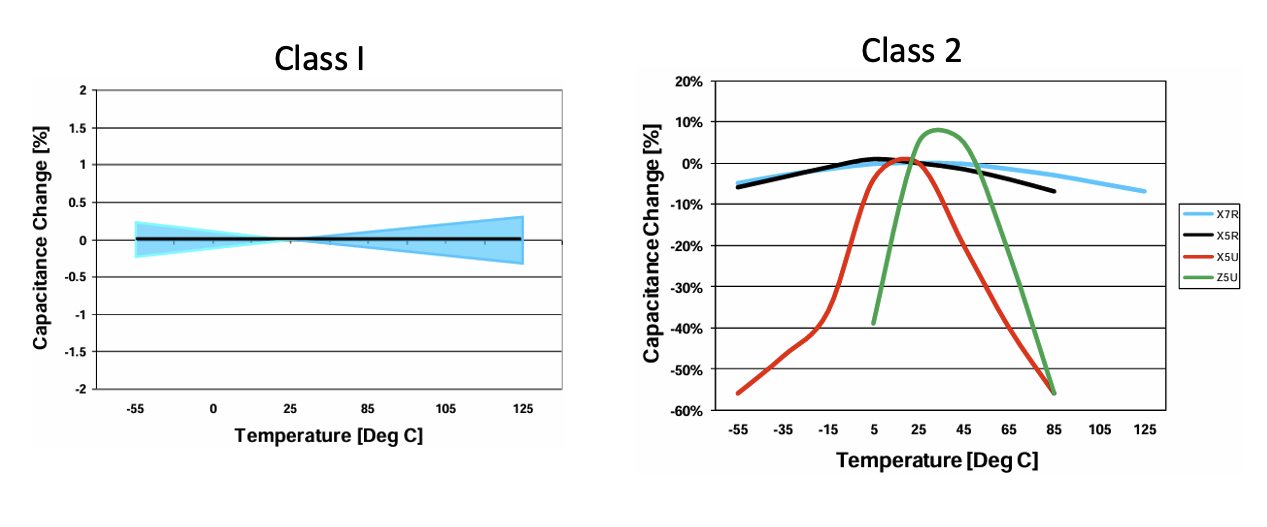
- Class I ceramics generally perform faster and provide higher stability than Class II ceramics.
- Class II ceramics (like X7R) may offer higher energy densities but are sometimes too slow for very fast pulse requirements.
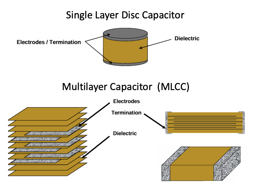
- Ceramic capacitor designs yield excellent power per unit volume.
- In extreme high-voltage scenarios, single-layer ceramic discs can achieve voltage ratings up to 50kV, and capacitor assemblies can be engineered for ratings greater than 100kV.
Understanding Energy and parasitics
To properly integrate a pulse capacitor, engineers must account for the device's equivalent circuit. No capacitor is perfect; they all exhibit losses known as parasitics, which are inherent to the dielectric material or the construction design.
Key parameters to consider include:
- Energy Density: Because stored energy increases with the square of the voltage (E = ½CV²), high-voltage pulse capacitors can deliver substantially greater energy during discharge.
- Equivalent Circuit Losses: The equivalent circuit includes the ideal capacitance (C) alongside unwanted properties like ESR, ESL, parallel resistance (Rp), and Insulation Resistance (IR) / Leakage Current.
- Resonance Frequency (fR): This is the frequency at which the capacitor ceases to behave as a capacitor and begins displaying inductive behavior. At fR, the capacitive reactance (XC) and inductive reactance (XL) cancel each other out, meaning the total impedance (Z) of the capacitor is equal to its ESR.
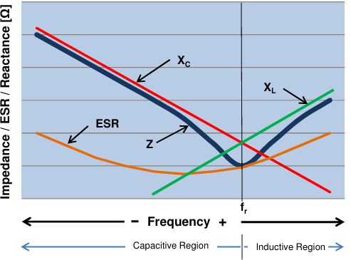
- Time Constant (τ): The time constant (τ = RC) dictates how fast a capacitor can discharge. It takes 5τ (or 5 × (ESR × C)) for a capacitor to be considered fully discharged. Therefore, ESR has a direct impact on the time constant and the resonance frequency.
Pulse Discharge Dynamics in Circuit Design
In a typical pulse discharge circuit, the instantaneous current can be calculated using the formula I = C × (dV/dt). To optimize this output, electronic engineers must minimize resistance and inductance in their designs. The faster the electron delivery is required, the more difficult the design becomes. Best practices include creating the shortest and straightest conductive paths possible when dealing with lead configurations, electrode geometry, and mounting.
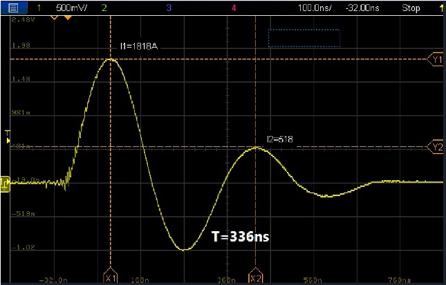
Interestingly, engineers can sometimes leverage parasitic inductance. In an underdamped circuit—where (4 × L/C) > R²—the inductance can be utilized to achieve an exceptionally high peak current during the pulse waveform.
The pulse discharge capacitor market is positioned for sustained growth due to defense modernization and medical imaging advancements. Because parasitic and performance characteristics dictate component selection, ceramic capacitors remain an integral part of modern technology, offering low ESR/ESL, superior frequency response, and exceptionally high voltage ratings ideal for rapid energy bursts.
Updated at: September 25, 2026.
Authors
David Zawacki (Vice President / Managing Director Exxelia CalRamic)
Andrew Schweber (Technical Sales Manager Exxelia CalRamic)
Michael Roach (Technical Sales Manager Exxelia CalRamic)
ISO
9001
certification
MIL-PRF
49462
qualified