EDICON China

Exxelia is exhibiting at EDICON China, Shanghai. From April 25 to 27 at booth#122, the company will be previewing several new microwave and RF components dedicated to a variety of industries including medical, transportation and defense.


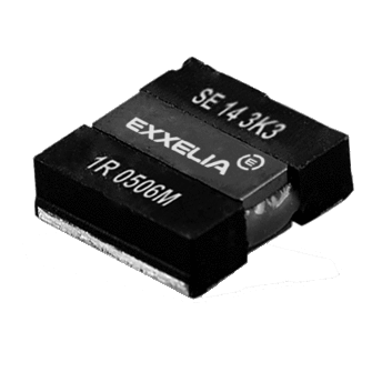
Ultra low ESR, high RF power and high self-resonant frequency               
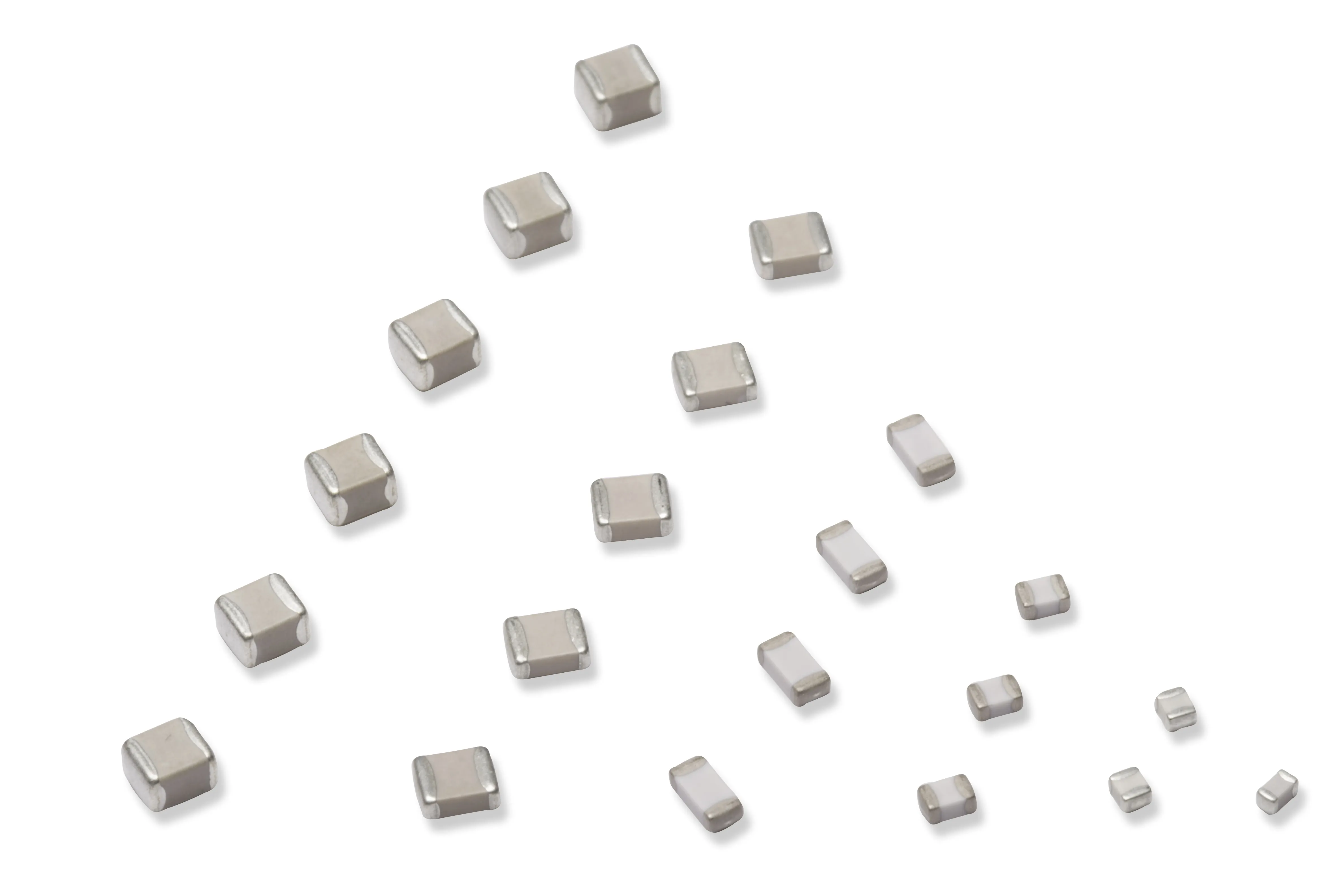
The new NHB series is a complete range of MLCC based on NPO dielectric material providing a very high Self Resonant Frequency and limiting the parasite Parallel Resonant Frequencies. The series is available in 1111 size with capacitance ranging from 0. 3pF to 100pF. NHB series offers excellent performance for RF power applications at high temperature up to 175°C and at 500 VDC. The lowest ESR is obtained by combining highly conductive metal electrodes and proprietary of new NPO low loss rugged dielectrics. NHB series particularly fits for high power and high frequency applications such as: cellular base station equipment, broadband wireless service, point to point / multipoint radios and broadcasting equipment. Typical circuit applications: impedance matching, bypass, feedback, tuning, coupling and DC blocking.

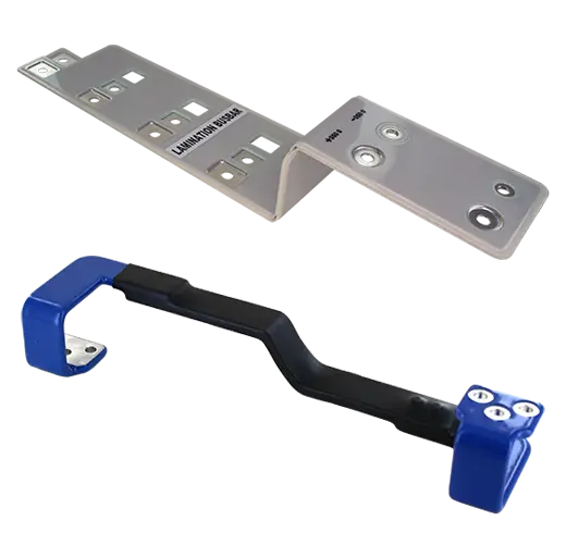
100% invar tuning screws with self-locking system         
Invar ScrewsEnsemble SIC SAFCO 1
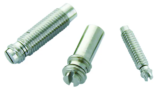
Invar-36 is a unique Iron-Nickel alloy (64 % Fe / 36 % Ni) sought-after for its very low coefficient of thermal expansion. With 1.1 ppm. K–1 between 0°C and 100°C, Invar-36 is about 17 times more stable than Brass which is the most traditional and common alloy Tuning Elements are made of. The working temperature range in Space is so wide that this property becomes essential for a reliable and stable cavity filter tuning. Self-locking system is a technology commonly used on Tuning Element made of Brass or other soft “easy-to-machine” alloys but is innovative and pretty advanced when applied to hard and tough Invar 36. The design consists of two threaded segments separated by two parallel slots. After cutting both parallel slots, the rotor is compressed in its length in order to create a plastic deformation. Thus, an offset is induced between the two threaded segments which generates a constant tensile stress in the rotor from the moment threaded segments are screwed.

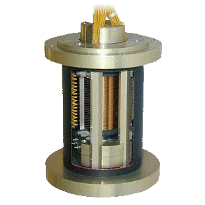
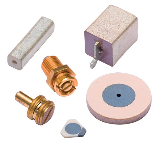
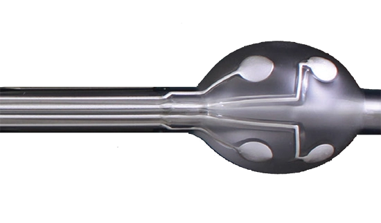
High Q Factor Dielectric Resonators
E7000 photo
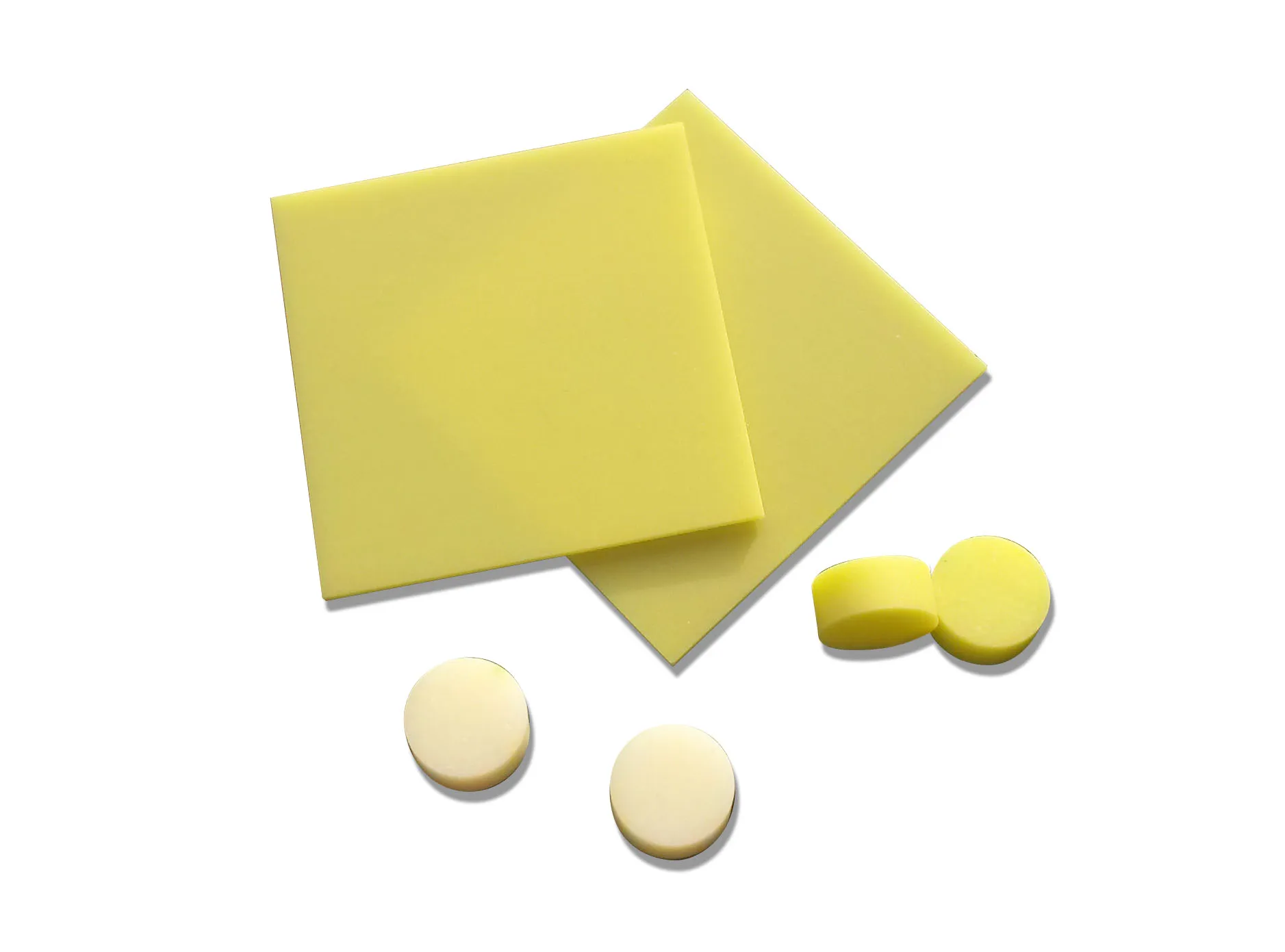
Dielectric resonators are designed to replace resonant cavities in microwave functions such as filters and oscillators. Exxelia has developed with support of ESA and CNES, a new high-end dielectric material, E7000 series, designed for high-end filters where high Q factor is requested.
E7000 is Ba-Mg-Ta materials based that combines an ultra-high Q factor and the possibility to get all the temperature coefficients upon request. E7000 provides high-performance requested for space use in the frequency range 5 to 32 GHz, and guarantees up to Qxf > 250 000 at 10GHZ. Typical applications: Satellite multiplexing filter devices, radio links for communication systems (LMDS), military radars.

Published on 03 Apr 2017 by Marion Van de Graaf

Exxelia onboard Solar Orbiter

Solar Orbiter, a European Space Agency mission, was launched on an Atlas V rocket 411 (AV-087) from Space Launch Complex 41 at Cape Canaveral Air Force Station at 11:03 p.m. EST on Sunday, Feb. 9 2020. The satellite reached its first working orbit around the Sun, called “halo orbit” and is ready to begin its first scientific observation campaign. The campaign will last six months, during which time the 55 payloads will be turned on one by one and tested before being used to perform scientific observations. Solar Orbiter is a highly complex scientific laboratory. Deploying such a mission is a one-of-a-kind achievement! The mission will take years and is one of the most highly anticipated scientific experiments of our time. And you know what they say: your best work comes when you're up against the toughest challenges. Unfortunately, these challenges aren't only in labs, but also in space. To study the Sun and its activity like never before, scientists are sending a probe into orbit around it. Solar Orbiter will be facing temperatures of up to 500°C, which is usually not survivable for complex equipment. But do you know what's even more challenging than getting data from a 500°C hot solar environment? Getting that data with expensive equipment that doesn't work, because you don't have enough reliable components at your disposal! That's why we, at Exxelia, were so happy when we heard that thousands of our capacitors and magnetics were chosen by the European Space Agency to achieve this mission; we're talking about components that will keep working in those kinds of harsh environments! They will help scientists better understand energy flow and particle acceleration within our own solar system and beyond. Shockingly, the Sun is mostly a mystery. We have some understanding of its composition, but it's unclear how the phenomena we see happen. Solar Orbiter is going to help us get a better idea of what makes the Sun tick by taking some of the most detailed images and observations of our star ever taken. Among the instruments on Solar Orbiter are: a Wide-Angle Imager and a Coronal Imager. Each will provide high-resolution images—an order of magnitude higher than those captured by NASA's Solar Dynamics Observatory—and spectacular views of the Sun's polar regions. The Wide-Angle Imager will capture images in five wavelengths, while the Coronal Imager will use seven wavelengths to observe phenomena that affect the upper layers of the solar atmosphere, such as magnetic fields and plasma flows. Our capacitors and magnetics are critical for stabilizing and powering these instruments on their mission to explore our home star! They need to be able to perform in a very hostile environment with temperatures ranging from -150°C (-238°F) to 500°C (932°F). Temperatures will reach their highest during the closest flybys of the Sun—which will take place as close as 15 million kilometers (about 93 million miles) from its surface. Our space capacitors and magnetics are capable of withstanding such high temperatures. They'll even keep functioning in cryogenic conditions, as low as -150°C (-238°F). These components are also very durable, which makes them perfectly suited for this mission.     Choosing the right capacitors for such a mission was not easy. The requirements and technical constraints were very strict. We had also to support and select the materials that could handle the launch vibrations and the shock of the rocket launching phase, we also had to achieve a very long life and high reliability in order to succeed in the mission. This project proves that our EXXELIA components are incredibly reliable and have nothing to envy to other electronic components on the market. Several other tests have been conducted by ESA in this project such as solar radiation, thermal shock... Exxelia ESA QLP Products Onboard Solar Orbiter : 14,400 CNC chips ceramic capacitors 14,400 CEC chips ceramic capacitors 520 of our CNC stacks ceramic capacitors 470 SESI QPL Inductors 380 MSCI RF Inductors  287 ESA qualified CTC21/E Tantalum Capacitors 50 ESA Film Capacitors PM94

High Voltage Resistor Selection Checklist

Introduction to High Voltage Resistor Selection Checklist The resistor is the most common and well-known passive electrical component. A resistor is a device connected into an electrical circuit to introduce a specified resistance. The resistance is measured in Ohms. As stated by Ohms Law (E=IR), the current through the resistor will be directly proportional to the voltage across it and inversely proportional to the resistance. Resistors have numerous characteristics that determine their accuracy during use. The performance indices affect the accuracy to a greater or lesser extent depending on the application. Some of these indices are: Tolerance at DC, Temperature Coefficient of Resistance (TCR), Voltage Coefficient of Resistance (VCR), Noise, Stability with respect to Time and Load, Power Rating, Physical Size, and Mounting Characteristics. Resistor networks typically require temperature and voltage tracking performance. Please refer to the application note: Glossary of Resistor Terminology for an expanded explanation of resistor terminology. Selection Requirements 1. Determine the resistance in ohms and watts. 2. Determine the proper physical case size as controlled by voltage, watts, mounting conditions, and circuit design requirements. 3. Select the resistor that meets your needs for type, termination and mounting. Step 1 : Determine the resistance in ohms and watts. Ohm’s Law: E=IR or I=E/R or R=E/I Ohm’s Law, as shown in the above formula, enables one to define the voltage (E), current (I), or resistance (R) when two of the three terms are known. When current and voltage are unknown they must be measured in the model circuit.   Power Law: W=I2R or W=EI or W=E2 /R Watts (power) can be determined from the above formulas that are derived from Ohm’s Law. R is measured in Ohms, E in volts, I in amperes, and W in watts. Watts must be accurately determined before resistor selection. Simply stated any change in voltage or current produces a much larger change in wattage (heat dissipated by the resistor). The effects of relatively small increases in voltage or current must be determined because the increase in wattage may be significant enough to influence resistor selection. As stated in the above formulas the wattage varies as the square of the current or voltage. Allowances should be made for maximum possible voltage. Step 2 : Determine the proper physical case size as controlled by voltage, watts, mounting conditions, and circuit design requirements. Power Rating and Physical Size: A resistor operated at a constant wattage will reach a steady temperature that is determined largely upon the ratio between the substrate size (surface area) and the wattage dissipated. Temperature stabilizes when the sum of the heat loss rates (by radiation, convection, and conduction) equals heat input rate (wattage). The larger the resistor surface area per watt to be dissipated, the greater the heat loss rate and therefore the lower the temperature rise. Free Air Wattage Rating (Maximum Power Rating) is defined as the wattage rating of resistors as established under specified standard conditions. The absolute temperature rise for a specific resistor is roughly related to the area of its radiating surface. It is also dependent upon a number of other factors such as thermal conductivity, ratio of length to width, heat-sink effects of mounting, and other minor factors. The precise temperature limits corresponding to 100% rated wattage are somewhat arbitrary and serve primarily as design targets. Once a wattage rating has been assigned on the basis of an empirical hot spot limit, the verification of its correctness must be established through long term load life test (see Application Note: Life Test Data – High Voltage Chip Resistors) based on performance and stability standards rather than the measurement of hot spot temperature. Step 3 : Select the resistor that meets your needs for type, termination and mounting. ✔ Resistor Selection: Select the most suitable resistor that meets the requirements of the application. OhmCraft resistors are made to your specification. Refer to the appropriate data sheet to determine part number or call OhmCraft for assistance. ✔ Wattage Rating: To allow for the differences between actual operating conditions and the Free Air Wattage Rating it is a general engineering practice to operate resistors at less than the nominal rating. ✔ Voltage Rating: Determine maximum applied (working) voltage that the resistor will be exposed to and select the appropriate package size. ✔ Pulse Operation: When a resistor is operated in a pulse application, the total power dissipated by the resistor is a function of the pulse’s duty cycle. Typically, one will define the number of joules of energy the resistor must dissipate and choose a resistor accordingly. For additional information refer to our Pulse Resistor white paper or contact OhmCraft. ✔ High Frequency: OhmCraft resistors, due to their design and construction, have very low capacitance and are inherently a non-inductive design. For additional information refer to our High Frequency Attributes Application Note. ✔ Military and Other Specification: The special physical operating and test requirements of the applicable industrial or military specification must be considered. Contact OhmCraft for additional information. Effect of the power ratings on components All the components of an electrical apparatus including resistors, capacitors, rectifiers, and semiconductors have their own limitations as to the maximum temperature at which they can reliably operate. The attained temperature in operation is the sum of the ambient temperature plus the temperature rise due to the heat dissipation in the equipment. Ambient Temperature Derating, below defines the percent of full load that power resistors can dissipate as a function of ambient temperature. Temperature Coefficient of Resistance Temperature Coefficient of Resistance (TCR) is expressed as the change in resistance in ppm (0.0001%) with each degree of change in temperature Celsius (C). MIL STD 202 Method 304 is often referenced as a standard for measuring TCR. This change is not linear with temperature. TCR is typically referenced at +25C and changes as the temperature increases or decreases. It can be either a bell or S shaped curve. It is treated as being linear unless very accurate measurements are required, then a temperature correction chart is used. A resistor with a TCR of 100 ppm will change 0.1% over a 10-degree change and 1% over a 100-degree change. An example of a TCR curve can be found in the application note: Glossary of Resistor Terminology. The following formula expresses the rate of change in resistance value per 1 C in a prescribed temperature range. TCR (ppm/°C) = (R-R0)/R0 X 1/(T-T0) X 106 - R: Measured resistance (Ω) at T °C - R0: Measured resistance (Ω) at T0 °C - T: Measured test temperature °C - T0: Measured test temperature °C In the context of a resistor network, this TCR value is called absolute TCR in that it defines the TCR of a specific resistor element. The term TCR tracking refers to the difference in TCR between each specific resistor in the network. Voltage Coefficient of Resistance The Voltage Coefficient of Resistance is the change in resistance with applied voltage. This is entirely different and in addition to the effects of self-heating when power is applied. A resistor with a VCR of 100 ppm/V will change 0.1% over a 10 Volt change and 1% over a 100 Volt change. VCR becomes very important in high Ohmic value resistor (100M Ω and above) where typical VCRs can be greater than 1000 ppm/V to specify the voltage that will be applied. Failing to do this may result in a resistor that will not meet your specification. The rate of change in resistance value per 1 volt in the prescribed voltage range is expressed by the following formula: VCR (ppm/V) = (R0-R)/ R0 X 1/(V0-V) X 106 - R: Measured resistance (Ω) at base voltage - R0: Measured resistance (Ω) at upper voltage - V: Base voltage - V0: Upper voltage In the context of a resistor network, this VCR value is called the absolute VCR in that it defines the VCR of a specific resistor element. The term VCR tracking refers to the difference in VCR between each specific resistor network. Please refer to the application note: Voltage Ratio Tracking and Voltage Coefficient of Resistance. Summary When specifying a resistor, the following parameters MAY be of interest. Please use this chart to help you define the operating characteristics for your specific application. All of them may not important for your specific application. Also, please do not hesitate to contact Ohmcraft for application help. At Exxelia Ohmcraft, our commitment transcends the creation of resistors. We are dedicated to empowering the visionary innovations that define the future of military technology. Our team is poised to collaborate and customize solutions that perfectly align with the evolving needs of military applications. In a landscape where reliability is non-negotiable and precision is imperative, Exxelia Ohmcraft stands as the beacon of unwavering support, fortifying military operations with resilient, high-performance resistors. Download our White Paper   Exxelia Ohmcraft’s sister division, Exxelia Micropen Medical is at the forefront of medical device product development, providing design engineers with unique insights on conceiving and implementing new designs and features.