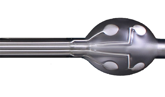
Exxelia Ohmcraft High voltage resistors in 3D dental imaging

To ensure the reliability of 3D imaging used by dentists, CBCT system manufacturers have relied on Exxelia Ohmcraft's custom high voltage resistors.


To capture adequate images of a patient’s teeth and jaw, dentists rely on advanced 3D imaging from cone-beam computed tomography (CBCT) systems. The CBCT system’s outputs are critical for the accurate diagnosis of oral health concerns and subsequent plans for treatment. To ensure the reliability of these images, manufacturers of CBCT systems have leveraged Exxelia Ohmcraft’s custom, high voltage resistors.

“In general, X-Rays require very high voltages to operate and generate clear, precise 3D images,” said Eric Van Wormer, Vice President of Exxelia Ohmcraft. “Because of the unmatched precision and control in surface-mount and leaded resistors from Exxelia Ohmcraft, manufacturers of this type of technology have turned to us to help ensure the reliability of their systems and the quality of the images they produce.”

CBCT systems are used to assist dentists in a variety of procedures, including dental implant placement, root canal therapy, the treatment of temporomandibular joint (TMJ) dysfunction, and oral surgery.

Exxelia Ohmcraft’s technology utilizes the proprietary Micropen electronic printing system to “print” precise, narrow, serpentine lines with resistive ink on a ceramic substrate, producing higher performance resistors over a wider range of values on a smaller surface area than is possible with conventional film resistor technology.

Published on 17 Mar 2021 by Valentine Taffineau

What you should know about Wound Magnetics Technologies ?

EXXELIA designs and manufactures magnetic components including wound magnetics, inductors, transformers, motors, sensors and actuators for high voltage, high temperature and power applications. Products are optimized to meet the most demanding applications requirement thanks to a strong design expertise, EXXELIA masters High-Grade technologies: Chameleon Concept Magnetics (CCM), standard linear and toroidal, toroidal transfer molded technology (TT), SESI planar / Low-profile and aluminum foil winding.   > See our Wound Magnetics Technologies in catalog   DESIGN CAPABILITIES Exxelia designs magnetics for most applications: Switch-mode power supply including new and unusual architectures 360-800Hz Power supply (single and multipulse) 50 Hz power supply Current and Voltage measurement Lighting - Ignition Pulse transformer (gate drive, data) Micro inductor Audio-frequency Electromagnets etc.   Exxelia designs magnetics up to: 200kV dielectric strength 20kV operating voltage … 240°C operating temperature According to the main aerospace standards ESA ESCC 3201 MIL-STD-981 MIL-PRF-27 D0-160 etc   SWITCHED MODE POWE SUPPLY Cross regulation in multi output Flyback converters Exxelia has been working on this subject in order to understand the phenomenon, identify the cause(s) and find solutions to avoid the use of linear regulators consuming energy The identification of a relevant magnetostatic model of the transformer and its electronic environment are necessary for analysis of the phenomenon into circuit simulation software like PSIM or PSPICE. This allows to evaluate the influence of the model parameters and the other components of the converter on the variability of output voltages. The key point is then to link the product manufacturing technology to the parameters of the model, in order to reduce cross regulation thanks to the optimization of windings arrangement. The work on this topic allows a precise control of the output voltages on the most sensitive windings. Dual Active Bridge, small size & high efficiency The dual active bridge is a topology more and more used to supply batteries because it allows bidirectional energy transfer with the network. Exxelia is developing high reproducibility technology to integrate inductors in the transformer:   Example : 3 Transformers in each power supply Each transformer incorporates virtual inductance Lk 15 kW combined output @ 100 kHz switching Taps provide flexibility for 350 V / 700 V input & 28 V or 56 V output (up to 430 A) Exxelia value proposition: Small size, high efficiency, competitive cost despite multiple high current outputs and integrated inductors.   360-800Hz MULTI PULSE Exxelia developed a specific knowledge to optimize the design of single and multi-pulse magnetics for 360 – 800 Hz power network.   ACCURATE MEASUREMENT TRANSFORMERS (0.1%) FOR CRITICAL APPLICATIONS Real-time, detailed knowledge of the voltages and currents is becoming increasingly important to ensure the proper operation of electrical networks. This is as true for the aeronautics market as it is for the industrial market. Measurement transformers, whether current or voltage, are sensors. They must faithfully transmit a signal level in a highly variable environment (excitation, frequency, temperature) which influences their characteristics. Exxelia developed a designing method that takes into account all environmental conditions. The behavior of the sensor is modeled by a transfer function that depends on transformer characteristics and on the load resistance. Depending on the application and the targeted accuracy, Exxelia defines the best operating point of the sensor by calculating the worst case errors with respect to the variability of the model parameters. Exxelia designs sensors with an accuracy of up to 0.1%.   THERMAL MANAGEMENT, A PATH TO MINIATURIZATION For Exxelia, better thermal management translates into miniaturization of the component.  Indeed, thanks to an accurate calculation of the maximum operating temperature, Exxelia can design the smallest component able to transfer a given power. The calculation of this temperature requires the knowledge of the heating sources (core and copper losses) and the component thermal behavior. Exxelia uses a calculation method to do the best use of core losses data and improve them by developing partnership with core manufacturer  The copper losses due to Eddy current are taken into account by Exxelia through the identification of the overriding causes and the use of the most relevant analytical approaches to evaluate them. The calculation of the operating temperature from the losses requires to determine the thermal resistance, which varies according to the ambient temperature, the power dissipated and the exchange conditions with the environment. Exxelia performs measurement campaigns to determine the thermal resistances and their variation for its qualified technologies and for most of the standard ferrite shapes. In particular, the influence of natural convection is taken into account to address products for Space. When more detailed analysis is required, Exxelia has developed a unique thermal simulation software, based on finite element calculation and dedicated to magnetic components to make its use easier and faster.    HIGH VOLTAGE AND ELECTRIC FIELD CALCULATION   Exxelia developed specific design skills to anticipate voltage increase requested for aircraft and space embedded application. High voltage topic is mastered with both dedicated test equipment (up to 100kV) and electric field calculation knowhow.  Electric Field mitigation: In high voltage applications, local high electric field E [kV/mm] can lead to a premature aging of intulating parts ou insulators? (Partial discharge) and finally to an electric failure.  Simulation in the design phase, using finite element calculations with a 2D or 3D electrostatic software allows Exxelia to reduce high field areas and increase lifetime. Example: Electric Field, Iso-Voltage values   Custom High Voltage Transformer   ELECTROMECHANICAL DEVICES Exxelia engineers use advanced finite-elements simulation software to model and analyse electromagnetic behaviour. EXXELIA can provide a high added-value support for electromechanical devices optimization through electromagnetic and thermal calculations (weight reduction, torque increase, losses reduction, etc…): •   2D and 3D calculations:     Magnetostatic: B[T], J[A/mm²], L matrix (function of current)     Electrostatic: E[kV/mm], C matrix     Eddy current (AC) in magneto-harmonic     2D transient coupled multiphysics (electric + magnetic + circuit) •   Specific analysis:     Optimization under constraints     Parametric analysis     Sensitivity analysis CAD geometry and circuit import/export (step, Catia, Spice, … ) Some calculations: Torque [N.m], Force [N], Resistance [Ω], Losses[W], L matrix [H], C matrix [F]  Some applications: linear or angular electric motor, electromagnet, linear or angular actuator, proportional valves, position sensor, etc… Proportional Hydraulic Valve Topology analysis: Based on an extensive experience, Exxelia can offer the best topology dedicated to an application or look for the best performance within a given space:   Torque, field and geometrical optimization   > See our Wound Magnetics Technologies in catalog How Exxelia supports the key processes ? Cleaning procedure  The cleaning of the PCB boards is evolving from solvent (as isopropylic alcohol,...) to highly alkaline water based cleaning medium.  EXXELIA has performed an extensive study to offer robust technologies to withstand these current cleaning processes. The qualification procedure has included thermal shock, burn in and   Mechanical testings.  EXXELIA has defined gluing, marking, varnishing processes that allow the products to go through more than 5 cleaning cycles and operating up to 180°C.  Processes compliant to ESA and NASA outgassing standards have also been defined for products specified up to 140°C.    Wire integrity  EXXELIA has qualified specific processes to ensure wire integrity for better insulation. The wire undergoes mechanical, chemical and thermal stresses during the winding and cabling process steps. EXXELIA has set up a dedicated process to reduce the impact of these manufacturing steps and improve the overall reliability of the wires and products.    Finishing  EXXELIA offers several types of components: Surface Mounted Device, Through Hole or lead terminations products, system integrated components.    Packaging  Products are available on trays and, upon request, on reels for easy pick and place, ESD compliant  EXXELIA products offer components compliant to IPC/JEDEC standard J-STD- 020 with TP = 260°C and tP = 30 seconds.  Exxelia is a manufacturer of complex passive components and precision subsystems focusing on highly demanding end-markets, applications and functions. Exxelia product portfolio includes wide ranges of capacitors, inductors, transformers, resistors, filters, position sensors, slip rings and high-precision mechanical parts serving numerous leading industrial areas such as aerospace, defense, medical, rail, energiy and telecommunications. Thanks to extensive design capabilities and a robust development process, Exxelia is recognized for its ability to quickly evaluate application specific engineering challenges and provide cost-effective and efficient solutions. For requirements that cannot be met by our catalog products, we offer custom configurations: upgraded performance, custom geometries, robust packaging. EXXELIA Magnetics business unit has more than 40 years experience in the design, industrialization and manufacturing of magnetics for Space, Civil Aviation, Defense, Oil & Gas, Medical, Railway and Industrial niche markets. EXXELIA actively works in partnership with the customer from prototype phase to production series.  EXXELIA has several production sites including low cost factories. All Magnetics sites are EN/AS9100 qualified. EXXELIA can therefore offer the most competitive solution to the customer.  EXXELIA offers PCB mounted components, ruggedized medium power magnetics subassemblies as well as stators & rotor and actuators. EXXELIA has a large technology portfolio including High-Grade platforms for demanding market and a strong manufacturing heritage. The customer benefits from EXXELIA design expertise and know-how for their design to specifications and built-to-print requests. Both catalog and custom products are available. The qualification of technological innovation and the definition of the related design rules allow EXXELIA to offer cost effective optimized solutions.    Customer benefits  Time to market: Available qualified technologies for harsh environment Strong heritage in Space   Optimised solutions:  Co-design through partnership with technical teams High expertise in complex designs Knowledge of the applications Industrialisation know how    Cost effective solutions: Reduced Non recurrent Cost, Low Cost Country Sites   Obsolescence management.   > See our Wound Magnetics Technologies in catalog EW SPACE, Constellation, SPACE 4.0: EXXELIA is the right choice due to strong space heritage, qualified technologies and multiple choice of manufacturing locations: USA, Asia, North Africa, Europe.   Quality System & Validation Capabilities EXXELIA masters, fully implements and maintains all the main international and customer standards, specifications, regulations and requirements for the design, manufacture, inspection and testing of magnetic components and for EHS and quality management:   Space magnetics:     Europe:             ESA: ESCC 3201 family of specifications,         ESCC 20400, ESCC 20500, ESCC 23500     QPL series:         ESCC32/008, ESCC3201/009 & ESCC3201/010     QML     ESCC3201/011 & ESCC3201/012    Technology Flow:     CNES:    RNC-CNES-Q-ST-60102, RNC-CNES-Q-60103     USA - Japan:    MIL-STD-981, MIL-PRF-27 Aeronautics and Military magnetics:     USA:             MIL-STD-981, MIL-PRF-27, MIL-HDBK-1553,         MIL-PRF-15305, MIL-PRF-21038, MIL-PRF-39010,         MIL-PRF-83446. Environmental conditions and tests:      Europe:    EUROCAE ED-14, ,     USA:     RTCA DO-160, MIL-STD-202. Environment, health and safety:     EC 1907/2006 (REACH), 2002/95/EC (RoHS) EXXELIA is manufacturing RoHS products by default. Non RoHS should be specifically requested.  EXXELIA maintains a comprehensive and up to date data base of all chemicals to closely follow the REACH status.  Quality management: EN/AS9100 and 1509001 family of standards Major aerospace customers standards. > See our Wound Magnetics Technologies in catalog

High Voltage Resistor Selection Checklist

body { background-color: #f9f9f9; color: #333; line-height: 1.6; font-size: 18px; } .main-heading { color: #00A160; /* Shamrock primary color */ font-size: 28px; padding: 10px 20px; background-color: #effaf1; /* Light green background for contrast */ border-left: 5px solid #00A160; margin: 30px 0 20px 0; border-radius: 4px; box-shadow: 0 2px 5px rgba(0,0,0,0.1); } .sub-heading { color: #365160; /* Bootstrap danger red */ font-size: 24px; margin-left: 40px; margin-top: 15px; border-bottom: 2px solid #365160; display: inline-block; padding-bottom: 5px; } .sub-sub-heading { color: #198754; /* Bootstrap success green */ font-size: 20px; margin-left: 60px; margin-top: 10px; background-color: #effaf1; /* Light green background for contrast */ padding: 5px 10px; border-radius: 4px; display: inline; } .industry-sector { margin: 20px; padding: 20px; border: 1px solid #ddd; border-radius: 8px; background-color: #fff; box-shadow: 0 2px 4px rgba(0,0,0,0.1); } .sector-header { font-size: 22px; color: #00A160; /* Shamrock primary color */ margin-bottom: 15px; } .sector-content { margin-left: 20px; } .key-requirements, .technical-calculations { margin-top: 10px; } .key-requirements ul, .technical-calculations ul { list-style-type: none; padding: 0; } .calculation { margin-top: 5px; background-color: #eef9ff; /* Light blue background for contrast */ border-left: 4px solid #00A160; /* Shamrock primary color */ padding: 10px; font-size: 18px; border-radius: 4px; word-wrap: break-word; overflow-wrap: break-word; word-break: break-all; } .calculation code { color: #d63384; /* A contrasting color for the code */ } /* Enhance the calculation boxes */ .calculation { margin-top: 5px; background-color: #eef9ff; /* Light blue background for contrast */ border-left: 4px solid #00A160; /* Shamrock primary color */ padding: 10px; font-family: 'Courier New', Courier, monospace; /* Ensures the monospace font */ font-size: 16px; /* Sets the font size */ color: #005030; /* Sets the font color */ border-radius: 4px; display: block; /* Ensures the element is treated as a block */ white-space: pre; /* Maintains whitespace as in the editor */ } /* Make sure code elements inside calculation boxes inherit the correct styles */ .calculation code { background-color: transparent; /* Avoids overriding the background */ color: inherit; /* Inherits the color from the parent .calculation */ font-family: inherit; /* Inherits the font-family from the parent .calculation */ padding: 0; /* Removes padding */ border: none; /* Removes any borders */ white-space: inherit; /* Inherits whitespace handling */ } /* You may also need to add !important to some properties if they are still being overridden */ 1. Project Specification Analysis Application Analysis ✅ Aviation Operational Environment: High altitudes, varying atmospheric pressures, and temperatures. Key Requirements: Vibration Resistance: Resistors must withstand continuous vibrations. Temperature Variability: Functionality across a broad temperature range. Technical Calculations: Vibration Stress = (Force/Area) * [1 - (Damping Coefficient * Frequency)] ✅ Space Operational Environment: Extreme temperatures, vacuum conditions, and radiation. Key Requirements: Radiation Hardness: Resistance to ionizing radiation effects. High Reliability: Low failure rates due to inaccessibility for repairs. Technical Calculations: Absorbed Dose (Gray) = Energy (Joules) / Mass (Kilograms) ✅ Defense Operational Environment: Battlefield conditions, including exposure to extreme elements and potential electromagnetic interference. Key Requirements: Ruggedness: High durability under physical and environmental stress. EMI/RFI Shielding: Protection against electromagnetic and radio-frequency interference. Technical Calculations: Shielding Effectiveness (SE) = 20 * log₁₀(E₁ / E₂), where E₁ and E₂ are electric field strengths. ✅ Medical Operational Environment: Sterile, controlled, and sensitive to electronic noise. Key Requirements: Precision and Stability: High accuracy for critical measurements. Biocompatibility: Safe for use in or near the human body. Technical Calculations: Safety Margin = Desired Performance / Actual Performance ✅ Energy Operational Environment: Power plants, substations, and renewable energy installations. Key Requirements: High Power Handling: Capacity to manage large currents and voltages. Surge Tolerance: Ability to withstand electrical surges. Technical Calculations: Thermal Dissipation = Power (Watts) = Voltage² / Resistance (Ohms) ✅ Mass Transportation Operational Environment: Trains, buses, and other public transport systems, often outdoor. Key Requirements: Robustness: Durability in fluctuating environmental conditions. Consistency: Reliable performance under continuous use. Technical Calculations: Mechanical Stress = Stress = Force / Area, considering dynamic loads during transportation. ✅ Telecommunications Operational Environment: Data centers, transmission stations, and communication devices. Key Requirements: Signal Integrity: Minimal impact on signal quality. Power Efficiency: Optimized for high-frequency operation. Technical Calculations: Attenuation (dB) = 10 * log₁₀(Power_in / Power_out) ✅ Industry Operational Environment: Factories, automation systems, and harsh industrial settings. Key Requirements: Environmental Resistance: Withstand dust, chemicals, and mechanical stress. Load Capacity: Suitable for high-load and continuous operations. Technical Calculations: Load Capacity = Load (Watts) = Voltage² / Resistance, ensuring capacity for industrial applications. Electrical Requirements ✅ Voltage Range Description: The range of voltage that the resistor must handle during normal operation. Key Considerations: Maximum Operating Voltage: The highest voltage the resistor can withstand without degradation. Minimum Operating Voltage: The lowest functional voltage for the resistor. Technical Calculations: Voltage Stress = Applied Voltage / Rated Voltage Safety Margin = (Rated Voltage - Maximum Operating Voltage) / Rated Voltage ✅ Current Profile Description: Analysis of current levels that the resistor will encounter, including average and peak currents. Key Considerations: Average Operating Current: The typical current flowing through the resistor under normal conditions. Peak Current: The maximum current that may flow through the resistor, often in surge conditions. Technical Calculations: Power (Watts) = Current² (Amps) × Resistance (Ohms) Thermal Management: Determining heat dissipation needs based on current flow ✅ Power Dissipation Description: The ability of the resistor to dissipate energy in the form of heat. Key Considerations: Power Rating: The maximum power that the resistor can safely dissipate. Overload Conditions: The resistor's behavior under temporary power overloads. Technical Calculations: Derating Curve Analysis: Adjusting the power rating based on operating temperature Heat Generated (Joules) = I²Rt, where I is current, R is resistance, and t is time. ✅ Resistance Value and Tolerance Description: Specifies the resistor’s nominal resistance value and permissible deviation. Key Considerations: Nominal Resistance: The intended resistance value. Tolerance: The allowable deviation from the nominal resistance, expressed in percentage. Technical Calculations: Tolerance = (Actual Resistance - Nominal Resistance) / Nominal Resistance × 100% Worst-Case Scenario Analysis: Considering the extremes of the tolerance range in design calculations ✅ Frequency Response Description: The behavior of the resistor at different frequencies, especially in high-frequency applications. Key Considerations: Inductive and Capacitive Components: These can affect resistor behavior at high frequencies. Skin Effect: The tendency of alternating current to distribute itself unevenly within the conductor. Technical Calculations: Reactance (Ohms) = 2πfL for inductance, 1/(2πfC) for capacitance. Frequency Impact Analysis: Assessing how frequency variations affect the resistor's performance ✅ Temperature Coefficient Description: The rate at which the resistor's resistance value changes with temperature. Key Considerations: Positive/Negative Temperature Coefficient: Determines if resistance increases or decreases with temperature. Stability Over Temperature Range: The resistor's ability to maintain its characteristics across temperatures. Technical Calculations: ΔR/R₀ = α × ΔT, where ΔR is the change in resistance, R₀ is the original resistance , α is the temperature coefficient, and ΔT is the change in temperature.   2. Resistor Type and Material Selection   ✅ Resistor Composition Description: The physical and chemical composition of the resistor, which determines its properties and suitability for different applications. Key Types and Considerations: ➡ Metal Film Resistors: Characteristics: Good temperature stability, low noise, and high precision. Usage: Ideal for precision applications requiring stable performance.   ➡ Carbon Film Resistors: Characteristics: Inexpensive, widely available, but with larger temperature coefficients. Usage: General-purpose applications where cost is a factor.   ➡ Wirewound Resistors: Characteristics: High power ratings, excellent stability, but inductive. Usage: High-power applications, precision circuits, but not suitable for high-frequency circuits.   ➡ Thick and Thin Film Resistors: Characteristics: Versatile, with a balance between performance and cost. Usage: Common in consumer electronics, telecommunications, and automotive sectors.   ➡ Foil Resistors: Characteristics: Extremely precise and stable, low temperature coefficients. Usage: High-precision applications, calibration equipment, and laboratory standards. ✅ Electrical Characteristics Description: The key electrical properties of resistors that define their performance in a circuit. Key Characteristics: ➡ Resistance Value: Consideration: Selecting the nominal resistance value as per circuit requirements. Calculation: Based on Ohm’s Law and circuit design parameters.   ➡ Power Rating: Consideration: The maximum power the resistor can dissipate without damage. Calculation: Power (Watts) = Voltage (Volts) × Current (Amps); also consider derating factors based on temperature.   ➡ Voltage Rating: Consideration: The maximum voltage that can be applied across the resistor. Calculation: Linked to the resistor’s size and construction; generally provided by the manufacturer.   ➡ Tolerance: Consideration: The permissible deviation from the nominal resistance value. Calculation: Specified as a percentage (e.g., ±1%, ±5%). ✅ Material Properties Description: The specific properties of materials used in resistor manufacturing, which influence performance under different conditions. Key Properties: ➡ Thermal Conductivity: Affects the resistor's ability to dissipate heat.   ➡ Temperature Coefficient: Influences how resistance changes with temperature.   ➡ Corrosion Resistance: Determines longevity and reliability in harsh environments.   ➡ Mechanical Strength: Resistance to physical stress and vibration. ✅ Construction and Design Description: How resistors are constructed, including their physical design, which impacts their performance and application. Key Considerations: Surface Mount vs. Through-Hole: Smaller, suitable for automated assembly; preferred in compact electronics. Larger, easy for hand assembly; used in applications requiring higher power handling. Encapsulation and Coating: Protects against environmental factors like moisture, dust, and chemicals. Lead Configuration and Materials: Influences mechanical stability and ease of soldering.   3. Performance Parameters Analysis   ✅ Electrical Tolerance Description: The degree to which the actual resistance value can deviate from the nominal value. Key Considerations: Tolerance Levels: Common tolerances are ±1%, ±5%, and ±10%. Precision applications require tighter tolerances. Impact on Performance: Affects the accuracy and predictability of circuit performance. Technical Calculations: Tolerance = (Actual Resistance - Nominal Resistance) / Nominal Resistance × 100% Worst-Case Scenario Analysis: Evaluating circuit function under maximum tolerance deviation ✅ Temperature Coefficient Description: The rate at which the resistor's resistance value changes with temperature. Key Considerations: Positive/Negative Coefficient: Positive means resistance increases with temperature, and vice versa. Stability Over Temperature Range: Essential for applications with wide temperature variations. Technical Calculations: ΔR/R₀ = α × ΔT, where ΔR is the change in resistance, R₀ is the original resistance, α is the temperature coefficient, and ΔT is the change in temperature. ✅ Frequency Response Description: The behavior of the resistor at different frequencies. Key Considerations: Inductive/Capacitive Effects: Impact on the resistor's performance at high frequencies. Skin Effect: The tendency for AC current to concentrate near the surface of the conductor. Technical Calculations: Reactance (Ohms) = 2πfL for inductance, 1/(2πfC) for capacitance. Frequency Impact Analysis: Assessing how frequency variations affect performance ✅ Noise Characteristics Description: The intrinsic electrical noise generated by the resistor. Key Considerations: Thermal Noise: Generated due to thermal agitation of electrons, dependent on temperature and resistance. Voltage Coefficient: Noise variation with applied voltage. Technical Calculations: V_noise = sqrt(4kTRΔf), where k is Boltzmann's constant, T is temperature, R is resistance , and Δf is bandwidth. ✅ Power Rating and Derating Description: The maximum power a resistor can dissipate without damage. Key Considerations: Rated Power: Determined at a specific ambient temperature, usually 70°C. Derating Curve: Power rating decreases as operating temperature increases. Technical Calculations: Power (Watts) = Voltage (Volts) × Current (Amps) Derating Factor: Based on manufacturer’s derating curve, typically a linear reduction with temperature ✅ Pulse Load Handling Description: The resistor's ability to withstand transient or pulse loads. Key Considerations: Pulse Withstand Capability: Resistors must handle energy spikes without damage. Energy Rating: The amount of energy a resistor can absorb in a pulse. Technical Calculations: Energy (Joules) = ½ × C × V², where C is the capacitance and V is the voltage. ✅ Environmental and Mechanical Stability Description: Resistance to environmental and mechanical stresses. Key Considerations: Vibration and Shock Resistance: Essential for applications in harsh mechanical environments. Environmental Resistances: Performance under varying humidity, temperature, and chemical exposure. Technical Calculations: Stress Analysis: Based on mechanical load and mounting considerations Environmental Testing: Following industry standards (e.g., MIL-STD for military applications) ✅ Reliability and Longevity Description: The expected operational life and failure rate of the resistor. Key Considerations: Mean Time Between Failures (MTBF): An indicator of reliability over time. Wear-Out Mechanisms: Factors leading to degradation, such as temperature and voltage stress. Technical Calculations: MTBF Estimation: Based on historical data and stress testing results   4. Physical and Environmental Suitability   ✅ Mechanical Design Constraints Description: The physical dimensions and construction features of the resistor that must be compatible with the application. Key Considerations: Size and Footprint: Matching the physical space available in the device or circuit. Mounting Method: Surface mount or through-hole, affecting the mechanical stability and ease of assembly. Technical Aspects: Space Utilization: Calculation of space requirements based on component dimensions. Mechanical Stress Analysis: Stress = Force / Area; considering the impact of assembly and operation. ✅ Thermal Management Description: The ability of the resistor (and its environment) to handle heat generated during operation. Key Considerations: Heat Dissipation: Efficient thermal management to prevent overheating. Cooling Requirements: Need for additional cooling solutions like heat sinks or airflow. Technical Aspects: Thermal Resistance: Thermal Resistance (°C/W) = (T_junction - T_ambient) / Power Dissipated. Heat Sink Efficiency: Based on heat sink material and design. ✅ Environmental Resistance Description: The resistor's ability to withstand environmental factors such as humidity, temperature extremes, and corrosive atmospheres. Key Considerations: Humidity Resistance: Operation in high humidity without performance degradation. Temperature Extremes: Functionality across the intended operational temperature range. Corrosion Resistance: Suitability for use in potentially corrosive environments. Technical Aspects: Accelerated Life Testing: Simulating environmental conditions to test durability. Corrosion Rate Calculation: Corrosion Rate = Weight Loss / (Area × Time × Density). ✅ Durability and Lifespan Description: The overall robustness and expected operational life of the resistor under normal and stress conditions. Key Considerations: Material Fatigue and Wear: Long-term effects of operational stress on materials. Life Expectancy: Predicted lifespan based on construction and environmental exposure. Technical Aspects: Fatigue Analysis: Fatigue Life = (Stress Range / Fatigue Strength) × Cycles to Failure. Arrhenius Equation for Lifespan Prediction: Rate = A × e^(-Ea/(kT)), where Ea is activation energy, k is Boltzmann's constant, and T is temperature. ✅ Compliance with Standards and Regulations Description: Adherence to industry-specific standards and environmental regulations. Key Considerations: Industry Standards: Compliance with relevant standards (e.g., IEC, IEEE, MIL-STD). Environmental Regulations: Meeting requirements like RoHS for hazardous substances. Technical Aspects: Certification Verification: Ensuring the resistor meets specified standards. Regulatory Assessment: Evaluating components for compliance with environmental and safety regulations. ✅ Specialized Application Needs Description: Additional considerations for resistors used in specialized applications. Key Considerations: Vibration and Shock Absorption: For applications involving movement or mechanical impact. EMI/RFI Shielding: In environments with high electromagnetic or radio-frequency interference. Technical Aspects: Vibration Isolation Design: Calculating isolation requirements based on application. Shielding Effectiveness: SE = 20 * log₁₀(E₁ / E₂); measuring the effectiveness of EMI/RFI shielding.   5. Safety and Regulatory Compliance   ✅ Voltage and Power Safety Margins Description: Ensuring that resistors can handle voltages and power levels beyond their nominal ratings to account for unexpected surges or spikes. Key Considerations: Voltage Rating: The maximum voltage a resistor can handle; should be higher than the maximum system voltage. Power Rating: The ability of the resistor to dissipate power; should include a safety margin above the expected maximum. Technical Aspects: Overload Testing: Testing resistors at elevated voltages and power levels to ensure robustness. Safety Margin Calculation: Safety Margin = (Rated Value - Maximum System Value) / Rated Value × 100%. ✅ Certification and Standards Compliance Description: Adherence to international and national standards that ensure safety, reliability, and quality. Key Considerations: Industry Standards: Compliance with standards like IEEE, IEC, UL, etc., depending on the application. Specific Regulations: Adherence to sector-specific regulations (e.g., automotive, medical, military). Technical Aspects: Certification Verification: Checking for certifications from recognized standards organizations. Regulatory Compliance Testing: Conducting or reviewing tests that demonstrate compliance with relevant standards. ✅ Environmental and Health Regulations Description: Ensuring that resistor manufacturing and operation comply with environmental and health safety standards. Key Considerations: RoHS Compliance: Restriction of Hazardous Substances in electronic components. REACH Compliance: Regulation concerning the Registration, Evaluation, Authorisation, and Restriction of Chemicals. Technical Aspects: Material Analysis: Assessing materials used in resistors for restricted substances. Compliance Documentation: Maintaining records and certifications proving compliance. ✅ Quality Assurance Protocols Description: Implementing quality control measures throughout the manufacturing and testing processes. Key Considerations: ISO Certifications: Compliance with ISO quality management standards (e.g., ISO 9001). In-House Testing: Rigorous testing protocols during manufacturing to ensure consistent quality. Technical Aspects: Quality Control Processes: Establishment of standard operating procedures for quality assurance. Testing and Inspection Metrics: Defining and applying metrics for quality evaluation. ✅ Failure Mode and Effect Analysis (FMEA) Description: Systematically evaluating potential failure modes of resistors and their impact on the larger system. Key Considerations: Identify Potential Failure Modes: Understanding how a resistor might fail (e.g., open circuit, short circuit) and the likelihood of these events. Assess Impact on System Performance: Evaluating the consequences of each failure mode on the system's operation. Technical Aspects: FMEA Procedure: Creating detailed FMEA charts that list potential failures, their causes, effects, and severity. Risk Priority Number (RPN) Calculation: RPN = Severity × Occurrence × Detection. ✅ Electrostatic Discharge (ESD) Considerations Description: Managing the risks associated with electrostatic discharge, which can damage electronic components. Key Considerations: ESD Sensitivity: Understanding the susceptibility of resistors to ESD damage. ESD Protection Measures: Implementing handling and packaging practices to mitigate ESD risks. Technical Aspects: ESD Testing: Conducting tests like the Human Body Model (HBM) to assess ESD robustness. Grounding and Shielding Strategies: Developing procedures for safe handling and storage. 6. Longevity and Reliability Assessments ✅ Life Cycle Analysis Description: Estimating the operational lifespan of resistors under normal and stress conditions. Key Considerations: Operational Lifespan: Predicted duration of effective performance under typical use. Stress-Induced Wear: Impact of environmental and electrical stress on lifespan. Technical Aspects: Accelerated Aging Tests: Simulating long-term use to predict lifespan. Arrhenius Model for Lifetime Prediction: Lifetime ∝ e^(−Activation Energy / (Boltzmann Constant × Temperature)). ✅ Reliability Testing Description: Conducting tests to verify the reliability of resistors under various conditions. Key Considerations: Mean Time Between Failures (MTBF): The average time expected between failures in a population of resistors. Failure Rate Analysis: Evaluating the rate at which resistors are expected to fail. Technical Aspects: Environmental Stress Screening (ESS): Exposing resistors to extreme conditions to identify early failures. Statistical Reliability Analysis: Using statistical methods to estimate failure rates and MTBF. ✅ Failure Mode and Effects Analysis (FMEA) Description: Systematically examining potential failure modes of resistors and assessing their impact. Key Considerations: Potential Failure Modes: Identifying how a resistor might fail (e.g., open circuit, short circuit). Effects on System Operation: Understanding the consequences of each failure mode. Technical Aspects: FMEA Chart Creation: Developing detailed charts that list potential failures, causes, and effects. Risk Assessment: Calculating Risk Priority Number (RPN) to prioritize risk mitigation efforts. ✅ Environmental and Mechanical Stress Testing Description: Testing resistors’ performance under various environmental and mechanical stresses. Key Considerations: Temperature Cycling: Exposing resistors to temperature extremes. Vibration and Shock Tests: Assessing mechanical robustness. Technical Aspects: Test Protocols: Following industry-standard test procedures (e.g., MIL-STD, IEC). Stress Test Analysis: Evaluating changes in performance characteristics post-testing. ✅ Quality and Manufacturing Consistency Description: Ensuring that the manufacturing process consistently produces resistors of high quality. Key Considerations: Quality Control Processes: Implementing rigorous quality checks during production. Material Consistency: Ensuring uniformity in materials used for manufacturing. Technical Aspects: Statistical Process Control (SPC): Monitoring production processes to detect and control quality. Batch Testing: Periodic testing of samples from production batches. ✅ Manufacturer Reputation and Track Record Description: Evaluating the historical performance and reliability reputation of the resistor manufacturer. Key Considerations: Historical Performance Data: Looking at the past performance of products from the manufacturer. Customer Feedback and Reviews: Gathering insights from user experiences and industry feedback. Technical Aspects: Vendor Assessment: Conducting a thorough review of the manufacturer’s history and capabilities. Reliability Metrics Comparison: Comparing performance metrics against industry benchmarks.