Découvrez nos condensateurs à film de puissance haute performance

Vous recherchez des condensateurs de puissance ? Parmi sa large gamme, le condensateur à film FP 20-400-SP mérite une attention particulière pour ses capacités exceptionnelles de gestion de la puissance.


Présentation du FP 20-400-SP

Le FP 20-400-SP est un condensateur à film conçu pour exceller dans les applications de haute puissance. Voici ce qui distingue ce condensateur :


Exxelia Alcon Power film capacitors
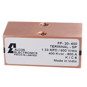
1. Haute densité de puissance : Le FP 20-400-SP présente une densité de puissance extraordinaire, ce qui en fait un choix idéal pour les applications où la puissance est essentielle. Sa capacité à gérer des niveaux de puissance élevés sans compromettre les performances témoigne de l'engagement d'Exxelia en faveur de l'excellence.

  • Fréquence de fonctionnement jusqu'à 1 000 KHz
  • Capacité : 0.10 µF - 2.5 µF
  • Voltage : 500 VRMS - 1 000 VRMS
  • Fréquence : 106 kHz - 637 kHz
  • Puissance maximale : 400 KVAR


2. Construction robuste : Il est construit pour résister aux rigueurs d'environnements exigeants, garantissant la fiabilité des applications critiques.

3. Large gamme de températures : ce condensateur à film fonctionne parfaitement dans une large gamme de températures (jusqu'à 85 °C avec un boîtier en cuivre pour améliorer la gestion de la température), ce qui le rend adapté à diverses industries, notamment l'aérospatiale, la défense, les énergies renouvelables, où les conditions extrêmes sont la norme.

Grâce à un process novateur, nous arrivons à garder un condensateur très dense tout en conservant des caractéristiques électriques très bonnes (tel que le courant) et cela sans venir dégrader l'échauffement de la pièce. 


Applications : Dans les circuits électroniques de puissance exigeants, ce condensateur est un composant fiable pour le bon fonctionnement du chauffage par induction, des voitures électriques, de l'imagerie médicale, des chargeurs sans fil pour les véhicules électriques.


Pour plus d'informations sur ce condensateur à film de puissance, visitez la fiche produit FP 20-400-SP d'Exxelia Alcon, ainsi que toute la famille des condensateurs à film de puissance Exxelia Alcon.


Exxelia Alcon Power film capacitors

Exxelia Alcon Power film capacitors

Exxelia Alcon Power film capacitors


Published on 30 Oct 2023 by Stephane PERES

High Voltage Resistor Selection Checklist

Introduction to High Voltage Resistor Selection Checklist The resistor is the most common and well-known passive electrical component. A resistor is a device connected into an electrical circuit to introduce a specified resistance. The resistance is measured in Ohms. As stated by Ohms Law (E=IR), the current through the resistor will be directly proportional to the voltage across it and inversely proportional to the resistance. Resistors have numerous characteristics that determine their accuracy during use. The performance indices affect the accuracy to a greater or lesser extent depending on the application. Some of these indices are: Tolerance at DC, Temperature Coefficient of Resistance (TCR), Voltage Coefficient of Resistance (VCR), Noise, Stability with respect to Time and Load, Power Rating, Physical Size, and Mounting Characteristics. Resistor networks typically require temperature and voltage tracking performance. Please refer to the application note: Glossary of Resistor Terminology for an expanded explanation of resistor terminology. Selection Requirements 1. Determine the resistance in ohms and watts. 2. Determine the proper physical case size as controlled by voltage, watts, mounting conditions, and circuit design requirements. 3. Select the resistor that meets your needs for type, termination and mounting. Step 1 : Determine the resistance in ohms and watts. Ohm’s Law: E=IR or I=E/R or R=E/I Ohm’s Law, as shown in the above formula, enables one to define the voltage (E), current (I), or resistance (R) when two of the three terms are known. When current and voltage are unknown they must be measured in the model circuit.   Power Law: W=I2R or W=EI or W=E2 /R Watts (power) can be determined from the above formulas that are derived from Ohm’s Law. R is measured in Ohms, E in volts, I in amperes, and W in watts. Watts must be accurately determined before resistor selection. Simply stated any change in voltage or current produces a much larger change in wattage (heat dissipated by the resistor). The effects of relatively small increases in voltage or current must be determined because the increase in wattage may be significant enough to influence resistor selection. As stated in the above formulas the wattage varies as the square of the current or voltage. Allowances should be made for maximum possible voltage. Step 2 : Determine the proper physical case size as controlled by voltage, watts, mounting conditions, and circuit design requirements. Power Rating and Physical Size: A resistor operated at a constant wattage will reach a steady temperature that is determined largely upon the ratio between the substrate size (surface area) and the wattage dissipated. Temperature stabilizes when the sum of the heat loss rates (by radiation, convection, and conduction) equals heat input rate (wattage). The larger the resistor surface area per watt to be dissipated, the greater the heat loss rate and therefore the lower the temperature rise. Free Air Wattage Rating (Maximum Power Rating) is defined as the wattage rating of resistors as established under specified standard conditions. The absolute temperature rise for a specific resistor is roughly related to the area of its radiating surface. It is also dependent upon a number of other factors such as thermal conductivity, ratio of length to width, heat-sink effects of mounting, and other minor factors. The precise temperature limits corresponding to 100% rated wattage are somewhat arbitrary and serve primarily as design targets. Once a wattage rating has been assigned on the basis of an empirical hot spot limit, the verification of its correctness must be established through long term load life test (see Application Note: Life Test Data – High Voltage Chip Resistors) based on performance and stability standards rather than the measurement of hot spot temperature. Step 3 : Select the resistor that meets your needs for type, termination and mounting. ✔ Resistor Selection: Select the most suitable resistor that meets the requirements of the application. OhmCraft resistors are made to your specification. Refer to the appropriate data sheet to determine part number or call OhmCraft for assistance. ✔ Wattage Rating: To allow for the differences between actual operating conditions and the Free Air Wattage Rating it is a general engineering practice to operate resistors at less than the nominal rating. ✔ Voltage Rating: Determine maximum applied (working) voltage that the resistor will be exposed to and select the appropriate package size. ✔ Pulse Operation: When a resistor is operated in a pulse application, the total power dissipated by the resistor is a function of the pulse’s duty cycle. Typically, one will define the number of joules of energy the resistor must dissipate and choose a resistor accordingly. For additional information refer to our Pulse Resistor white paper or contact OhmCraft. ✔ High Frequency: OhmCraft resistors, due to their design and construction, have very low capacitance and are inherently a non-inductive design. For additional information refer to our High Frequency Attributes Application Note. ✔ Military and Other Specification: The special physical operating and test requirements of the applicable industrial or military specification must be considered. Contact OhmCraft for additional information. Effect of the power ratings on components All the components of an electrical apparatus including resistors, capacitors, rectifiers, and semiconductors have their own limitations as to the maximum temperature at which they can reliably operate. The attained temperature in operation is the sum of the ambient temperature plus the temperature rise due to the heat dissipation in the equipment. Ambient Temperature Derating, below defines the percent of full load that power resistors can dissipate as a function of ambient temperature. Temperature Coefficient of Resistance Temperature Coefficient of Resistance (TCR) is expressed as the change in resistance in ppm (0.0001%) with each degree of change in temperature Celsius (C). MIL STD 202 Method 304 is often referenced as a standard for measuring TCR. This change is not linear with temperature. TCR is typically referenced at +25C and changes as the temperature increases or decreases. It can be either a bell or S shaped curve. It is treated as being linear unless very accurate measurements are required, then a temperature correction chart is used. A resistor with a TCR of 100 ppm will change 0.1% over a 10-degree change and 1% over a 100-degree change. An example of a TCR curve can be found in the application note: Glossary of Resistor Terminology. The following formula expresses the rate of change in resistance value per 1 C in a prescribed temperature range. TCR (ppm/°C) = (R-R0)/R0 X 1/(T-T0) X 106 - R: Measured resistance (Ω) at T °C - R0: Measured resistance (Ω) at T0 °C - T: Measured test temperature °C - T0: Measured test temperature °C In the context of a resistor network, this TCR value is called absolute TCR in that it defines the TCR of a specific resistor element. The term TCR tracking refers to the difference in TCR between each specific resistor in the network. Voltage Coefficient of Resistance The Voltage Coefficient of Resistance is the change in resistance with applied voltage. This is entirely different and in addition to the effects of self-heating when power is applied. A resistor with a VCR of 100 ppm/V will change 0.1% over a 10 Volt change and 1% over a 100 Volt change. VCR becomes very important in high Ohmic value resistor (100M Ω and above) where typical VCRs can be greater than 1000 ppm/V to specify the voltage that will be applied. Failing to do this may result in a resistor that will not meet your specification. The rate of change in resistance value per 1 volt in the prescribed voltage range is expressed by the following formula: VCR (ppm/V) = (R0-R)/ R0 X 1/(V0-V) X 106 - R: Measured resistance (Ω) at base voltage - R0: Measured resistance (Ω) at upper voltage - V: Base voltage - V0: Upper voltage In the context of a resistor network, this VCR value is called the absolute VCR in that it defines the VCR of a specific resistor element. The term VCR tracking refers to the difference in VCR between each specific resistor network. Please refer to the application note: Voltage Ratio Tracking and Voltage Coefficient of Resistance. Summary When specifying a resistor, the following parameters MAY be of interest. Please use this chart to help you define the operating characteristics for your specific application. All of them may not important for your specific application. Also, please do not hesitate to contact Ohmcraft for application help. At Exxelia Ohmcraft, our commitment transcends the creation of resistors. We are dedicated to empowering the visionary innovations that define the future of military technology. Our team is poised to collaborate and customize solutions that perfectly align with the evolving needs of military applications. In a landscape where reliability is non-negotiable and precision is imperative, Exxelia Ohmcraft stands as the beacon of unwavering support, fortifying military operations with resilient, high-performance resistors. Download our White Paper   Exxelia Ohmcraft’s sister division, Exxelia Micropen Medical is at the forefront of medical device product development, providing design engineers with unique insights on conceiving and implementing new designs and features. 

A “Game Changer” Rectangular Aluminum Electrolytic Capacitor, Called Cubisic SLP

Cubisic SLP is the new rectangular aluminum electrolytic capacitor from EXXELIA, a world leader in manufacturing and designing capacitors. Their products are known for their high performance and reliability, which has made them the choice of many of the world's leading avionics engineering companies. However, they were looking for a new, more reliable capacitor that could withstand even greater vibration and altitude than any previous capacitor. They needed a stronger, more reliable product with a life expectancy that matched the customers' projects. Product description : Cubisic SLP is among the industry's first aluminum electrolytic capacitors designed with flat technology. The result is a lighter, smaller rectangular shape with increased surface area, which improves its capacity. As a result, it can accommodate more energy at almost any altitude or vibration level.    This makes Cubisic SLP ideal for applications where added durability is required, such as cockpits and power generation functions on aircrafts, along with being well-suited for radars and laser systems in up to 50G vibration conditions and 92K feet altitude resistance. ✅ Low profile printed circuit mounting ✅ Possible mounting with 45 x 12 bracket (A691057) ✅ Possible thermal dissipation per conduction through a lower and upper surface ✅ Switch mode power supplies, impulse current ✅ Withstands more than 92,000 feet altitude ✅ Sleeve optional Cubisic SLP comes in three sizes, is made with high-quality aluminum foil and impregnate with electrolyte. It has 2 terminals: anode, cathode. What makes Cubisic SLP so different? An example of one of the advantages of this technology is that designing a capacitor with a traditional cylindrical shape, means that 2/3 of its volume is empty, compared to this new flat design. As a result, more capacitors are packed into the same volume, thus increasing the density. What’s a Rectangular Aluminum electrolytic capacitor, and why is that important? What’s, a Rectangular Aluminum electrolytic capacitor : In short (no pun intended), a rectangular electrolytic capacitor is one of those components that keeps your electronics running safely, your ship floating, and your aircraft operating properly.  A Rectangular electrolytic capacitor is a component that essentially stores electrical energy in the form of an ‘electrolyte’. It’s made up of three layers: two aluminum sheets separated by an electrolyte solution and encased in a steel or porcelain container. And as the name implies, it’s shaped like a rectangle. It's widely used in different industries because of its reliable and cost-effective protection, which makes it the go-to component for many commercial, industrial, and aerospace uses. Rectangular aluminum electrolytic capacitors are mostly used in military aircrafts, missiles, and nautical transportation, as well as space navigation systems. In these applications, reliability is crucial for the safety of millions of people, so it is essential to choose a reliable product that offers high performance and quality. So if you find yourself with any of those use cases and/or engineering projects on your hands that require high performance and quality under extreme environments, look no further than this capacitor! Why is that important? As an example, when a military fighter jet accelerates, it can experience up to three times the force of gravity. While this is an impressive feat, consider what it does to the components in the vehicle. One such component is a capacitor. While it might seem like just a small piece of circuitry, capacitors are responsible for a variety of functions in your fighter jet, including: > Powering the radar antenna > Controlling engine performance > Controlling flight-related functions like fuel injection and landing gear operation This is because of the way they deal with heat buildup, which is an issue with capacitors in high-performance vehicles, especially on aircrafts where rapid acceleration can cause significant damage to any component. That's helpful in the cockpit, where the controls are exposed to this kind of force; a control that has to withstand up to three times the force of gravity will last longer than one that isn't designed for this. In other places on a military jet—such as power generation functions—the same principle applies: if something is going to be exposed to extreme forces (like vibration or acceleration), it needs to be strong enough not to break easily. That's why these capacitors are a great choice: they can handle extreme conditions without losing their effectiveness over time. That's why Exxelia takes the time to test every single capacitor we sell to our customers. How does its ability to withstand varying vibration levels and altitudes make a difference to the aerospace industry? What makes a rectangular aluminum electrolytic capacitor so effective for aerospace companies? The answer: They're made from high-quality material—pure and simple. But the difference between standard capacitors and those for the aerospace industry goes far beyond that. For the aerospace industry, the ideal capacitor would endure extreme temperatures, have a wide range of voltage tolerances, and withstand varying vibration levels, all while maintaining its effectiveness at an altitude of 19,000 meters—which is where Cubisic SLP comes in. As an electrolytic capacitor with an expanded operating temperature range and a very high resistance against vibration and altitude changes, this product has been able to make a huge difference in how well aircrafts can stay in control. Not only does it help prevent power outages, but also it helps avionics to stay functional when they are subjected to drastically changing conditions. Cubisic SLP capacitors are designed to handle extreme environments, which makes them incredibly versatile—and incredibly useful. From aeronautics to medicine, these capacitors can help your projects meet just about any challenges. Where can I find out more about EXXELIA’s Cubisic SLP range? Radial aluminum electrolytic capacitors cubisic SLP Radial aluminum electrolytic capacitors cubisic HTLP Radial aluminum electrolytic capacitors alsic 145 20g Radial aluminum electrolytic capacitors alsic 20g Radial aluminum electrolytic capacitors cubisic lp Radial aluminum electrolytic capacitors cubisic   TECHNICAL PAPERS (Electrical characterization of cubisic SLP capacitors) DOWNLOAD DATASHEET