What you should know about Wound Magnetics Technologies ?

Discover the basic information about Wound Magnetics Technologies, to improve your choice


EXXELIA designs and manufactures magnetic components including wound magnetics, inductors, transformers, motors, sensors and actuators for high voltage, high temperature and power applications.

Products are optimized to meet the most demanding applications requirement thanks to a strong design expertise, EXXELIA masters High-Grade technologies: Chameleon Concept Magnetics (CCM), standard linear and toroidal, toroidal transfer molded technology (TT), SESI planar / Low-profile and aluminum foil winding.


See our Wound Magnetics Technologies in catalog


DESIGN CAPABILITIES

Exxelia designs magnetics for most applications:

  • Switch-mode power supply including new
  • and unusual architectures
  • 360-800Hz Power supply
  • (single and multipulse)
  • 50 Hz power supply
  • Current and Voltage measurement
  • Lighting - Ignition
  • Pulse transformer (gate drive, data)
  • Micro inductor
  • Audio-frequency
  • Electromagnets etc.


Exxelia designs magnetics up to:

  • 200kV dielectric strength
  • 20kV operating voltage …
  • 240°C operating temperature
  • According to the main aerospace
  • standards
  • ESA ESCC 3201
  • MIL-STD-981
  • MIL-PRF-27
  • D0-160 etc


SWITCHED MODE POWE SUPPLY


Cross regulation in multi output Flyback converters


Exxelia has been working on this subject in order to understand the phenomenon, identify the cause(s) and find solutions to avoid the use of linear regulators consuming energy
The identification of a relevant magnetostatic model of the transformer and its electronic environment are necessary for analysis of the phenomenon into circuit simulation software like PSIM or PSPICE. This allows to evaluate the influence of the model parameters and the other components of the converter on the variability of output voltages.
The key point is then to link the product manufacturing technology to the parameters of the model, in order to reduce cross regulation thanks to the optimization of windings arrangement.
The work on this topic allows a precise control of the output voltages on the most sensitive windings.


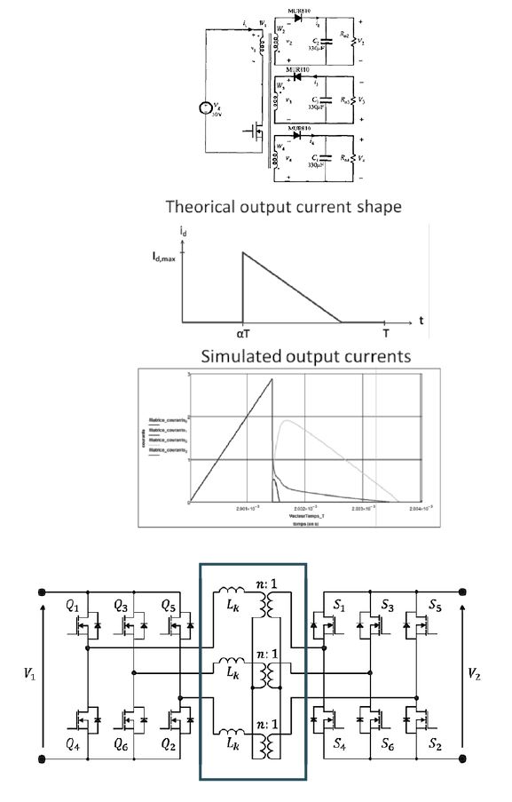
Dual Active Bridge, small size & high efficiency


The dual active bridge is a topology more and more used to supply batteries because it allows bidirectional energy transfer with the network.
Exxelia is developing high reproducibility technology to integrate inductors in the transformer:
 

Example :
3 Transformers in each power supply
Each transformer incorporates virtual inductance Lk
15 kW combined output @ 100 kHz switching
Taps provide flexibility for 350 V / 700 V input & 28 V or 56 V output (up to 430 A)
Exxelia value proposition: Small size, high efficiency, competitive cost despite
multiple high current outputs and integrated inductors.


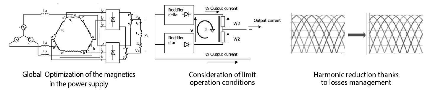
360-800Hz MULTI PULSE


Exxelia developed a specific knowledge to optimize the design of single and multi-pulse magnetics for 360 – 800 Hz power network.


ACCURATE MEASUREMENT TRANSFORMERS (0.1%) FOR CRITICAL APPLICATIONS


Real-time, detailed knowledge of the voltages and currents is becoming increasingly important to ensure the proper operation of electrical networks. This is as true for the aeronautics market as it is for the industrial market.
Measurement transformers, whether current or voltage, are sensors. They must faithfully transmit a signal level in a highly variable environment (excitation, frequency, temperature) which influences their characteristics.


Exxelia developed a designing method that takes into account all environmental conditions. The behavior of the sensor is modeled by a transfer function that depends on transformer characteristics and on the load resistance.
Depending on the application and the targeted accuracy, Exxelia defines the best operating point of the sensor by calculating the worst case errors with respect to the variability of the model parameters.


Exxelia designs sensors with an accuracy of up to 0.1%.


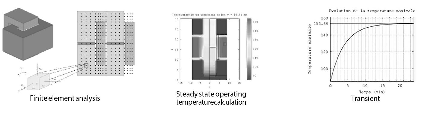
THERMAL MANAGEMENT, A PATH TO MINIATURIZATION


For Exxelia, better thermal management translates into miniaturization of the component
Indeed, thanks to an accurate calculation of the maximum operating temperature, Exxelia can design the smallest component able to transfer a given power.
The calculation of this temperature requires the knowledge of the heating sources (core and copper losses) and the component thermal behavior.


Exxelia uses a calculation method to do the best use of core losses data and improve them by developing partnership with core manufacturer 
The copper losses due to Eddy current are taken into account by Exxelia through the identification of the overriding causes and the use of the most relevant analytical approaches to evaluate them.


The calculation of the operating temperature from the losses requires to determine the thermal resistance, which varies according to the ambient temperature, the power dissipated and the exchange conditions with the environment.


Exxelia performs measurement campaigns to determine the thermal resistances and their variation for its qualified technologies and for most of the standard ferrite shapes. In particular, the influence of natural convection is taken into account to address products for Space.
When more detailed analysis is required, Exxelia has developed a unique thermal simulation software, based on finite element calculation and dedicated to magnetic components to make its use easier and faster. 


HIGH VOLTAGE AND ELECTRIC FIELD CALCULATION


Exxelia developed specific design skills to anticipate voltage increase requested for aircraft and space embedded application. High voltage topic is mastered with both dedicated test equipment (up to 100kV) and electric field calculation knowhow. 

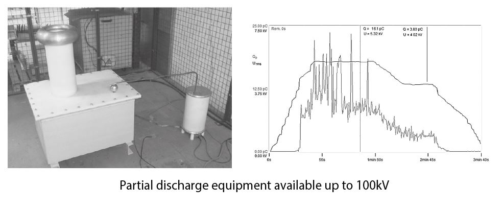
Electric Field mitigation:

In high voltage applications, local high electric field E [kV/mm] can lead to a premature aging of intulating parts ou insulators? (Partial discharge) and finally to an electric failure. 
Simulation in the design phase, using finite element calculations with a 2D or 3D electrostatic software allows Exxelia to reduce high field areas and increase lifetime.


Example: Electric Field, Iso-Voltage values


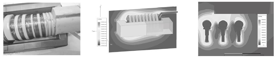
Custom High Voltage Transformer


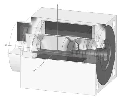
ELECTROMECHANICAL DEVICES


Exxelia engineers use advanced finite-elements simulation software to model and analyse electromagnetic behaviour.
EXXELIA can provide a high added-value support for electromechanical devices optimization through electromagnetic and thermal calculations (weight reduction, torque increase, losses reduction, etc…):


•   2D and 3D calculations:
    Magnetostatic: B[T], J[A/mm²], L matrix (function of current)
    Electrostatic: E[kV/mm], C matrix
    Eddy current (AC) in magneto-harmonic
    2D transient coupled multiphysics (electric + magnetic + circuit)


•   Specific analysis:
    Optimization under constraints
    Parametric analysis
    Sensitivity analysis


CAD geometry and circuit import/export (step, Catia, Spice, … )
Some calculations: Torque [N.m], Force [N], Resistance [Ω], Losses[W], L matrix [H], C matrix [F] 
Some applications: linear or angular electric motor, electromagnet, linear or angular actuator, proportional valves, position sensor, etc… Proportional Hydraulic Valve


Topology analysis:

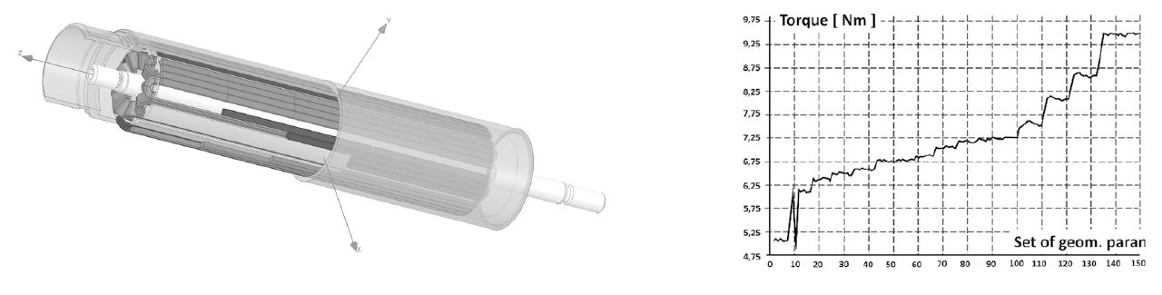
Based on an extensive experience, Exxelia can offer the best topology dedicated to an application or look for the best performance within a given space:


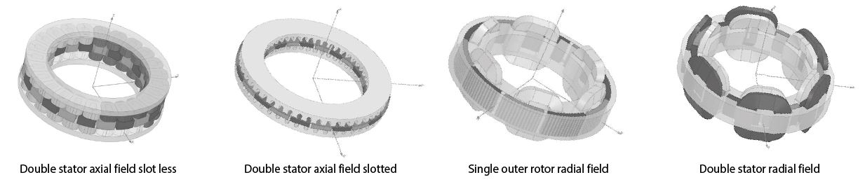
Torque, field and geometrical optimization


See our Wound Magnetics Technologies in catalog

How Exxelia supports the key processes ?


Cleaning procedure 

The cleaning of the PCB boards is evolving from solvent (as isopropylic alcohol,...) to highly alkaline water based cleaning medium. 
EXXELIA has performed an extensive study to offer robust technologies to withstand these current cleaning processes. The qualification procedure has included thermal shock, burn in and


Mechanical testings. 

EXXELIA has defined gluing, marking, varnishing processes that allow the products to go through more than 5 cleaning cycles and operating up to 180°C. 
Processes compliant to ESA and NASA outgassing standards have also been defined for products specified up to 140°C. 
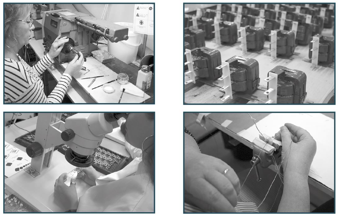
 

Wire integrity 

EXXELIA has qualified specific processes to ensure wire integrity for better insulation. The wire undergoes mechanical, chemical and thermal stresses during the winding and cabling process steps. EXXELIA has set up a dedicated process to reduce the impact of these manufacturing steps and improve the overall reliability of the wires and products. 


Finishing 

EXXELIA offers several types of components: Surface Mounted Device, Through Hole or lead terminations products, system integrated components. 


Packaging 

Products are available on trays and, upon request, on reels for easy pick and place, ESD compliant 
EXXELIA products offer components compliant to IPC/JEDEC standard J-STD- 020 with TP = 260°C and tP = 30 seconds. 

Exxelia is a manufacturer of complex passive components and precision subsystems focusing on highly demanding end-markets, applications and functions. Exxelia product portfolio includes wide ranges of capacitors, inductors, transformers, resistors, filters, position sensors, slip rings and high-precision mechanical parts serving numerous leading industrial areas such as aerospace, defense, medical, rail, energiy and telecommunications.
Thanks to extensive design capabilities and a robust development process, Exxelia is recognized for its ability to quickly evaluate application specific engineering challenges and provide cost-effective and efficient solutions. For requirements that cannot be met by our catalog products, we offer custom configurations: upgraded performance, custom geometries, robust packaging.

EXXELIA Magnetics business unit has more than 40 years experience in the design, industrialization and manufacturing of magnetics for Space, Civil Aviation, Defense, Oil & Gas, Medical, Railway and Industrial niche markets.

EXXELIA actively works in partnership with the customer from prototype phase to production series. 

EXXELIA has several production sites including low cost factories. All Magnetics sites are EN/AS9100 qualified. EXXELIA can therefore offer the most competitive solution to the customer. 

EXXELIA offers PCB mounted components, ruggedized medium power magnetics subassemblies as well as stators & rotor and actuators. EXXELIA has a large technology portfolio including High-Grade platforms for demanding market and a strong manufacturing heritage.
The customer benefits from EXXELIA design expertise and know-how for their design to specifications and built-to-print requests. Both catalog and custom products are available. The qualification of technological innovation and the definition of the related design rules allow EXXELIA to offer cost effective optimized solutions. 


Customer benefits 

  • Time to market:

Available qualified technologies for harsh environment
Strong heritage in Space


  • Optimised solutions: 

Co-design through partnership with technical teams
High expertise in complex designs
Knowledge of the applications
Industrialisation know how 


  • Cost effective solutions:

Reduced Non recurrent Cost, Low Cost Country Sites


  • Obsolescence management.


See our Wound Magnetics Technologies in catalog

EW SPACE, Constellation, SPACE 4.0:

EXXELIA is the right choice due to strong space heritage, qualified technologies and multiple choice of manufacturing locations: USA, Asia, North Africa, Europe.


Quality System & Validation Capabilities

EXXELIA masters, fully implements and maintains all the main international and customer standards, specifications, regulations and requirements for the design, manufacture, inspection and testing of magnetic components and for EHS and quality management:


Space magnetics:
    Europe:    

        ESA: ESCC 3201 family of specifications,
        ESCC 20400, ESCC 20500, ESCC 23500


    QPL series:    

    ESCC32/008, ESCC3201/009 & ESCC3201/010
    QML     ESCC3201/011 & ESCC3201/012


   Technology Flow:
    CNES:    RNC-CNES-Q-ST-60102, RNC-CNES-Q-60103
    USA - Japan:    MIL-STD-981, MIL-PRF-27


Aeronautics and Military magnetics:
    USA:    

        MIL-STD-981, MIL-PRF-27, MIL-HDBK-1553,
        MIL-PRF-15305, MIL-PRF-21038, MIL-PRF-39010,
        MIL-PRF-83446.


Environmental conditions and tests: 
    Europe:    EUROCAE ED-14, ,
    USA:     RTCA DO-160, MIL-STD-202.


Environment, health and safety:
    EC 1907/2006 (REACH), 2002/95/EC (RoHS)


EXXELIA is manufacturing RoHS products by default. Non RoHS should be specifically requested. 
EXXELIA maintains a comprehensive and up to date data base of all chemicals to closely follow the REACH status. 


Quality management:

EN/AS9100 and 1509001 family of standards
Major aerospace customers standards.

See our Wound Magnetics Technologies in catalog

Published on 26 Dec 2021 by Stephane PERES

How to Select the Right Precision Resistor for Your Needs

{ "@context": "https://schema.org/", "@type": "HowTo", "name": "How to Select the Right Precision Resistor for Your Needs", "description": "Learn how to choose the right precision high voltage resistor for your project and find the expert advice you need. Find out how to select the correct precision resistor for best performance.", "image": "https://exxelia.com/uploads/News/how-to-select-the-right-precision-resistor-for-your-needs-65772fa33dd61.png", "totalTime": "PT8M", "estimatedCost": { "@type": "MonetaryAmount", "currency": "USD", "value": "0" }, "step": { "@type": "HowToStep", "text": "" } } I. Introduction to Precision Resistors A. Overview of the Importance of Precision Resistors in Electronic Circuits Precision resistors are integral components in modern electronic circuits, playing a pivotal role in determining the performance and accuracy of these systems. Their primary function is to manage and regulate the flow of electric current, ensuring that other components within the circuit receive the correct amount of power. This precision is particularly crucial in applications requiring high degrees of accuracy and stability, such as in medical equipment, aerospace technology, and sophisticated measuring instruments. The reliability and accuracy of precision resistors directly impact the overall efficiency, reliability, and safety of these electronic systems. B. Explanation of How Precision Resistors Differ from Standard Resistors While standard resistors are used in everyday electronic devices for basic current regulation, precision resistors are engineered to offer much higher accuracy and stability. The key distinctions lie in their tighter tolerance levels, lower temperature coefficients, and superior long-term stability. Tolerance in resistors indicates the degree of variance permissible from their specified resistance value, and precision resistors have significantly lower tolerance levels compared to standard resistors. Additionally, precision resistors exhibit minimal change in resistance with temperature variations, making them ideal for applications where environmental conditions fluctuate. C. Brief Introduction to High Voltage Resistors as a Subset of Precision Resistors High voltage resistors are a specialized category within precision resistors, designed to operate reliably under high voltage conditions. These resistors are crucial in circuits where they must withstand and regulate large voltage levels without compromising performance or safety. They are constructed using materials and designs that can handle high energy loads, and they often feature specific construction techniques to prevent breakdowns or failures due to the high voltage environment. D. Statement Understanding the critical factors in selecting the right precision resistor, especially for high voltage applications, is essential for optimal performance and safety. The selection process involves a comprehensive understanding of various technical parameters, including voltage and power ratings, tolerance, temperature coefficient, and physical packaging. This knowledge ensures that the chosen resistor not only meets the specific needs of the application but also adheres to the highest standards of reliability and safety. Table: Comprehensive Technical Criteria for Selecting High Voltage Precision Resistors Criteria Sub-Criteria Key Considerations Technical Details Application Implications Voltage Rating Maximum Operating Voltage Highest voltage the resistor can handle without breakdown Values typically range from a few kilovolts (kV) to tens of kV; must exceed the maximum circuit voltage Ensures safety and reliability under peak voltage conditions Power Rating Power Dissipation Capacity Amount of power the resistor can dissipate as heat without damage Rated in watts (W); dependent on resistor size, material, and design Prevents overheating and thermal degradation, especially critical in high-load applications Tolerance Accuracy Level Acceptable range of resistance variation from the nominal value Expressed as a percentage (%); tighter tolerance indicates higher precision (e.g., ±0.1%, ±0.5%) Higher precision in control and measurement circuits; critical for calibration and testing equipment Temperature Coefficient Temperature-Dependent Resistance Change Rate at which resistance changes with temperature Expressed as parts per million per degree Celsius (ppm/°C); lower values indicate better stability Minimizes performance variance in fluctuating thermal environments; essential for outdoor and industrial applications Thermal Stability Long-term Resistance Stability at Operating Temperatures Ability to maintain consistent resistance over time at specific temperatures Assessed through accelerated aging tests and thermal cycling Ensures long-term reliability and accuracy in high-temperature applications Physical Size & Form Factor Dimensions and Mounting Style Physical dimensions and installation method of the resistor Includes through-hole, surface-mount, and custom designs; size influences heat dissipation Determines compatibility with circuit board layout and influences thermal management Packaging Material and Construction External materials and construction methods used Options include conformal coating, encapsulation, and use of flame-retardant materials Affects durability, heat dissipation, and environmental resistance (moisture, chemical exposure) Environmental Resistance Resistance to External Conditions Ability to withstand environmental stressors Includes moisture resistance, vibration tolerance, and chemical resistance Ensures stable operation in harsh conditions like high humidity, industrial settings, or mobile equipment The following sections will delve into these aspects in detail, providing a thorough guide for professionals in selecting the most suitable high voltage precision resistors for their specific requirements.     II. Understanding Precision Resistors A. Definition and Characteristics 1. Explanation of What Precision Resistors Are Precision resistors are components in electronic circuits designed to offer high accuracy in their resistance values. Unlike standard resistors, which may have significant variance in resistance, precision resistors are manufactured to have minimal deviation from their specified resistance values. This accuracy is critical in applications where precise control of current and voltage is necessary to ensure the proper functioning of sensitive and high-precision electronic equipment. 2. Key Characteristics: Tolerance, Temperature Coefficient, Noise, and Stability - Tolerance: This refers to the allowable deviation of a resistor's resistance value from its nominal value, expressed as a percentage. For precision resistors, tolerance values are typically much tighter, often below 1%, ensuring greater accuracy. - Temperature Coefficient: This is a measure of how much a resistor's resistance changes with temperature. Precision resistors have low temperature coefficients, meaning their resistance remains stable across a range of temperatures, which is vital for consistent performance. - Noise: In the context of resistors, noise is the random variation in resistance, which can affect the signal quality in sensitive circuits. Precision resistors are designed to minimize noise, ensuring cleaner and more reliable signal transmission. - Stability: This characteristic refers to the ability of a resistor to maintain its resistance value over time, despite environmental factors and usage. Precision resistors have high stability, ensuring long-term reliability. B. Types of Precision Resistors 1. Overview of Various Types - Metal Film: These resistors are known for their high accuracy and low noise. They are made by depositing a thin metal film on a ceramic body. - Wirewound: These are made by winding a metal wire around an insulating core. They are known for high power ratings and stability. - Foil: Foil resistors offer the highest precision and stability. They are made by bonding a metal foil onto a ceramic substrate. 2. Pros and Cons of Each Type in Different Applications - Metal Film: Pros include good temperature coefficient and low noise, making them suitable for precision analog circuits. However, they may not be ideal for high-power applications. - Wirewound: These resistors excel in high-power applications and have good temperature performance. Their downside is their inductance, which may not be suitable for high-frequency applications. - Foil: While offering unparalleled precision and stability, foil resistors can be more expensive and may not be necessary for applications where extreme precision is not required. C. Importance in High Voltage Circuits 1. Role and Significance in High Voltage Applications In high voltage circuits, resistors must handle and regulate large voltages without degradation or failure. Precision resistors in these applications ensure that voltage is managed accurately, which is crucial for the safety and effectiveness of the overall system. Their precision and stability are key in maintaining the integrity of high voltage circuits found in power supplies, medical equipment, and industrial machinery. 2. Challenges Posed by High Voltage Environments High voltage environments pose unique challenges for resistors. They must be designed to withstand high electric fields without breakdown. This includes considerations for dielectric strength, insulation resistance, and physical construction to prevent arcing and physical damage. The materials used must be able to endure these stresses while maintaining their resistive properties over time, ensuring long-term reliability and safety.     III. Criteria for Selecting High Voltage Resistors A. Voltage Rating and Power Rating 1. Understanding Voltage Rating and Its Importance The voltage rating of a resistor indicates the maximum voltage it can handle before it risks breakdown or damage. This is particularly crucial in high voltage applications where resistors are exposed to high potential differences. Selecting a resistor with an appropriate voltage rating is essential to prevent premature failure and ensure safety. The voltage rating must be higher than the maximum voltage expected in the circuit to accommodate transient spikes without compromising the resistor's integrity. 2. How Power Rating Affects Resistor Performance in High Voltage Circuits Power rating is a measure of how much power a resistor can dissipate without exceeding its maximum operating temperature. In high voltage circuits, resistors often encounter high power levels. If a resistor's power rating is too low, it can overheat and fail. It's essential to choose a resistor with a power rating that matches or exceeds the power levels in the circuit. This ensures that the resistor can operate reliably over its intended lifespan without degrading due to thermal stress. B. Tolerance and Accuracy 1. Importance of Tolerance in Precision Resistors Tolerance, the permissible deviation from the nominal resistance value, is critical in precision resistors. In high voltage applications, even small inaccuracies can lead to significant errors or malfunctions. Precision resistors with tight tolerance are essential for applications where precise control of voltage and current is necessary, such as in calibration equipment or high-accuracy measuring devices. 2. Balancing Tolerance and Cost in High Voltage Applications While tighter tolerance is generally desirable, it often comes at a higher cost. Therefore, selecting a resistor involves balancing the need for precision with budget constraints. It's important to evaluate the level of tolerance required for the application’s performance and safety, and choose a resistor that provides the necessary precision without unnecessary expense. C. Temperature Coefficient and Thermal Stability 1. Role of Temperature Coefficient in Resistor Performance The temperature coefficient of a resistor indicates how its resistance changes with temperature. A low temperature coefficient is desirable in high voltage applications, as it ensures that the resistor maintains a stable resistance across a range of operating temperatures. This stability is vital in environments where temperature variations are common, as it affects the accuracy and reliability of the circuit. 2. Managing Thermal Stability in High Voltage Environments In addition to selecting resistors with low temperature coefficients, managing thermal stability involves considering the resistor’s environment. Factors such as ventilation, heat sinks, and placement within the circuit can influence the resistor’s temperature. Proper thermal management ensures that resistors operate within their specified temperature range, maintaining performance and prolonging lifespan. D. Physical Size and Packaging 1. Considering Physical Constraints and Mounting Styles The physical size and form factor of a resistor are important in applications with space constraints or specific mounting requirements. In high voltage circuits, larger resistors might be necessary to ensure adequate spacing for preventing arcing or breakdown. The choice of mounting style (such as through-hole or surface-mount) also impacts the resistor's thermal management and mechanical stability. 2. Impact of Packaging on Heat Dissipation and Durability The packaging of a resistor affects its ability to dissipate heat and withstand environmental stresses. In high voltage applications, resistors must be packaged in a way that promotes efficient heat dissipation to prevent overheating. The materials used in the packaging should also be durable and resistant to environmental factors such as humidity, chemicals, or mechanical stress. This ensures the long-term reliability and performance of the resistor in demanding high voltage environments.     IV. Application-Specific Considerations A. Industry-Specific Requirements 1. Tailoring Resistor Selection to Industry Standards Different industries have unique standards and requirements that significantly influence the selection of precision resistors, especially in high voltage applications. - Aerospace: This industry demands resistors that can withstand extreme conditions such as high altitudes, temperature fluctuations, and vibrations. Resistors must comply with stringent standards for reliability and durability. For example, they often require a very low temperature coefficient and exceptional stability to ensure accurate performance in critical aerospace systems. - Medical: In medical applications, precision resistors are used in sensitive and life-supporting equipment. They must meet high safety standards, ensuring accuracy and reliability. Resistors in these applications often need to be highly precise, with low noise and minimal variability to ensure patient safety and accurate readings. B. Environmental Factors 1. Dealing with Environmental Challenges Environmental conditions such as humidity and temperature extremes play a significant role in the performance of high voltage resistors. - Humidity: High levels of moisture can affect the insulation properties of resistors, potentially leading to short circuits or degradation of components. Selecting resistors with appropriate moisture resistance and protective coatings is crucial in humid environments. - Temperature Extremes: Resistors must be chosen based on their ability to operate reliably under extreme temperatures. This involves selecting materials and designs that can withstand thermal expansion and contraction, as well as maintain their resistive properties across the specified temperature range. C. Customization for Special Requirements 1. When to Consider Custom Solutions for Unique Applications There are scenarios where standard precision resistors might not meet the specific requirements of a high voltage application. In such cases, custom-designed resistors become necessary. - Unique Electrical Requirements: If an application has unusual voltage, current, or power demands that standard resistors cannot meet, custom resistors can be designed to handle these specific requirements. - Physical Space Limitations: In applications where space is constrained, standard resistors might not fit. Custom resistors can be designed with specific sizes and shapes to fit into limited spaces without compromising performance. - Special Environmental Conditions: For applications operating in extreme or unusual environments, such as deep-sea exploration or space missions, custom resistors can be developed with materials and coatings specifically engineered to withstand these conditions.     V. Best Practices in Selecting High Voltage Precision Resistors A. Comprehensive Needs Assessment 1. Identifying Key Parameters Based on Application Needs Before selecting high voltage precision resistors, a thorough assessment of the application’s needs is essential. This involves identifying key parameters that will influence the choice of resistor. Important factors to consider include: - Voltage and Power Requirements: Determine the maximum voltage and power the resistor needs to handle. This ensures the resistor can operate safely under the highest expected loads. - Tolerance and Accuracy Needs: Assess the level of precision required in the application. High-precision applications may necessitate resistors with very tight tolerances. - Environmental Conditions: Consider the operating environment, including temperature ranges, humidity levels, and potential exposure to chemicals or mechanical stress. - Physical Space Constraints: Evaluate the available space for the resistor in the circuit, which will influence the size and form factor of the resistor. - Regulatory and Industry Standards: Identify any industry-specific standards or regulations that the resistors must comply with. B. Vendor Selection and Quality Assurance 1. Choosing Reputable Vendors for High-Quality Components The quality of precision resistors is largely dependent on the manufacturer. Selecting reputable vendors is crucial for ensuring the reliability and performance of the components. Look for vendors with: - Proven Track Record: Choose manufacturers known for their quality and reliability in the industry. - Expertise in High Voltage Applications: Select vendors with specific experience and expertise in manufacturing high voltage precision resistors. - Good Customer Support: A vendor who offers strong technical support can be invaluable, especially for custom applications or when addressing specific technical challenges. 2. Importance of Quality Certifications and Testing Quality certifications and thorough testing are vital for ensuring that the resistors meet the required standards and specifications. - Quality Certifications: Look for resistors that come with relevant quality certifications, such as ISO standards. These certifications indicate that the resistors have been manufactured and tested according to rigorous quality control procedures. - Product Testing: Ensure that the resistors have undergone appropriate testing for parameters such as tolerance, temperature coefficient, and long-term stability. This can include in-house testing by the manufacturer and independent third-party testing. In conclusion, selecting the right high voltage precision resistors involves a detailed needs assessment and careful consideration of various technical parameters. Partnering with reputable vendors and ensuring quality certifications and testing are also critical steps in the selection process. Following these best practices will help in acquiring resistors that meet the specific needs of high voltage applications, ensuring safety, reliability, and optimal performance.

CCM, a family of magnetic components dedicated to space applications and optimized for multi-output flyback converters

  INTRODUCTION   In the mid 2010s, EXXELIA decided to develop a family of products capable of withstanding the harsh environments of aerospace and especially space, and complementary to our existing SESI and TT families. We decided to develop Chameleon Concept Magnetics (CCM). The range currently consists of 5 sizes, CCM4/5/6 and CCM20/25. The maximum transferable power in the CCM25 is about 200W, depending on the operating conditions of the transformer. A CCM30 is currently under development. This would approach 350W. The internal construction of the CCMs is similar to that of the SESIs, but there are some differences. We wanted to optimise the reproducibility of the electrical characteristics. We defined sizes with many connections, to focus on multi-output applications. CCMs are more compact and higher than SESIs. Today, the raw materials used all have a thermal class of 180°C.   Figure 1 : Overview of the current CCM range     PART 1 : SPATIAL QUALIFICATION WITH ESA/CNES   The qualification of SESI concerned standard ranges of QPL differential mode chokes and common mode chokes. Over the years, we have seen more and more developments of specific, so non QPL products. In these cases, the technology used was space compatible, as the inductors were space compliant and the raw materials and manufacturing process were almost identical. However, these products did not have QPL status.   For the 5 sizes of the CCM family, we chose to do things differently in order to have a valid qualification for all types of functions, inductors and transformers. We chose to apply for and pass a Technology Know-How Approval (TKA), which has since become Technology Flow (TF). The principle of TF is to define precisely the technology with which products will be manufactured, associate to it design rules with it, evaluate the technology and then qualify it. Once the TF is obtained, any product that meets the technology and design rules has the status of qualified and can be used without further testing. This saves money and time. The TF consists of two successive phases whose objective is to demonstrate the reliability of the technology with respect to all the constraints that the component will have to undergo during its life. The first phase is the evaluation phase, the second is the qualification phase. The evaluation phase is the most important one, as it is the one that must show the robustness of the technology in all stress domains. It is on the initiative of EXXELIA. The qualification, supervised by CNES and ESA, only confirms the compatibility of the technology with the space environment on a limited number of tests and components representative of the whole range of sizes.   Before starting the tests, EXXELIA defined the framework of the CCM technology, i.e. two detailed and exhaustive lists, one for the raw materials and one for the manufacturing operations. With regard to raw materials, all categories were well defined: Magnetic circuits / cores : manufacturer(s) and material(s), Bobbins : dimensions and materials, Winding wires : manufacturer(s), grade of insulating enamel, thermal class, and diameters, Solid insulators: manufacturers and materials, Glues, resins and varnishes: manufacturer(s) and references, Solderings and fluxes, ESD packagings. With regard to manufacturing, all operations from winding to packaging were also detailed. Thus, with these two lists, the framework for CCM technology is perfectly clear. In addition to these manufacturing constraints, EXXELIA defined a quality framework including working methods, documents and a level of traceability compliant with space requirements.   For the evaluation phase, a large number of tests were planned and carried out in the following areas : thermal shocks, burn-in, life test, dielectric strength, internal component heating (Rth), shock and vibration mechanical resistance, brazing and soldering heat resistance, solderability, pin pull-out strength, marking resistance, and moisture resistance. In each area, a test procedure has been defined as well as the number of components involved. The ESCC3201 standard, which itself is based on several MIL standards, was used as a guide throughout the evaluation campaign, which took much time. Several hundred parts were manufactured, tested and even destroyed. In fact, in several areas, we pushed the components beyond their limits in order to determine the safety margins available to us. In all aspects, particularly thermal, mechanical and long-term reliability, we have found that they are sufficient for the needs of space.   This evaluation campaign was a success. It was the subject of a report [1] sent to ESA. The qualification phase then took over. It too was a success. A complementary document was created to follow the qualification evolutions of this technological family.   We now had a space-qualified technology family that allowed us to design a wide range of components for our customers' applications. We now needed to know in detail how our components would behave in the customer's environment.   PART 2 : THERMAL, FREQUENCY AND SATURATION BEHAVIOURS   In order for our customers to choose the right component for their application, we need to provide them with a set of information on the behaviour of our components. We therefore decided to carry out three characterisation campaigns : thermal, frequency and saturation.   Thermal characterisation   Internal heating of components is becoming an increasingly important aspect, taking into account the increase in the ratio of power by weight and power by volume in equipment. EXXELIA has therefore launched several actions in this field. One of them is to improve our knowledge of the thermal behaviour of two of its standard component families, CCMs and TTs. During the qualification of CCMs, a campaign had already been carried out in this field. The results were neither sufficiently precise nor sufficiently complete to meet our needs for information and advice to customers. Ideally, mathematical models of thermal resistance in vacuum or measurements in vacuum should have been available quickly. Both of these are possible, but they are very time-consuming because the mathematical study involves the physics of fluid mechanics, and making thermal measurements in vacuum is complex. As a first step, we decided to carry out a characterisation campaign with natural convection in air, which will serve as a reference for the ongoing studies in vacuum. Conduction and radiation, which play a significant role in the calorie extraction, are indeed present in both air and vacuum. In addition to the dependence on component characteristics, Rths vary according to several external parameters, in particular : Ambient temperature, Environment (carrier PCB/other, air/vacuum, horizontal/vertical layout, and so on), Power level to be dissipated in the component, i.e. the losses, Location of these losses, in the windings (copper), or in the magnetic circuit (iron core). EXXELIA has already carried out this type of experimental characterisation in the 2000s for the SESI family of components. The objective of this study was to carry out the same work on the CCM and TT families. We only detail the CCM part.   The components are SMD. They are single-winding inductors. For simplicity of calculation of the losses, sources of heating, we chose to supply the inductors with direct current. The component winding resistances are between 5mΩ and 2Ω at room temperature. The excitation conditions are such that the maximum temperature rises bring the components to a temperature of about 180°C, which is the thermal class of all raw materials used in CCMs. The temperature of the component is measured via the winding resistance measurement. The law of variation of copper conductivity with temperature is taken into account and it is assumed that the temperature gradient in the different parts of the component, moulding and magnetic circuit, is small compared to the overall rise in ambient temperature. The component is supplied for a sufficient time to reach the stabilised thermal steady state. For each size, Rth measurements are made at six different ambient temperatures: 25, 50, 75, 100, 125 and 150°C. For each ambient temperature, we first determine the power point that brings the component to around 180°C. For the curve at 25°C ambient temperature, fifteen measurements of Rth are made at injected powers equally distributed between 0 and the maximum power determined previously. For the curves at higher ambient temperatures, the same power points are used, except those leading to maximum temperatures above 180°C. Two inductance values are characterised for each of the 5 sizes, i.e. 10 components to be tested. All components are soldered onto a PCB similar to that used for SESI characterisation. The temperature of the PCB is measured throughout the tests to identify any increase in temperature. A 112 liter ventilated oven was used. Care was taken to protect the components from ventilation inside a box. The box was defined that was large enough in comparison to the volume of the largest component to be characterised. It was perforated at the top and bottom to allow natural convection between the box and the ventilated airflow outside. The temperature inside the box was measured to identify any rise in its average temperature.   We are not going to detail more the development of the experimental bench here, but it was an important part of the work. In particular, we analysed in detail the study and the setting up of the box inside the oven, the monitoring of the different temperatures as well as all the metrology used, in particular the accuracy of the results. We also made comparative measurements at 22°C inside the oven and outside in order to verify that the oven had a sufficiently small influence on the results. Figure 2 below shows the synoptic of the bench.   Figure 2 : Synoptic diagram of the test bench   Figure 3 below shows an example of the curve obtained for a CCM20 6K8. The Rth values on the y-axis have been removed.   Figure 3 : Rth in air versus power dissipation curves for a CCM20 6K8   Once all the curves were obtained, several checks were made, firstly on the shape of a curve. The Rth decreases with the power dissipated and also with the ambient temperature, which seems to be consistent with the laws of thermics. We also compared the curves from one size to another. We are convinced that the curves obtained are close to the reality of the thermal behaviour of the component placed in this environment. It should be remembered that the role of the environment is fundamental. A provisional conclusion of all the actions underway in this thermal project is that a component has as many Rth as the environments in which it is placed.   As mentioned above, these curves for natural convection in air are to be considered as a reference. Characterisation in vacuum and the construction of a mathematical model of the thermal resistances of CCMs are underway. The results should be available in 2023.   Frequency characterization   It was concretely a question of drawing for each selected component an inductance curve as a function of frequency under constant excitation at room temperature For each of the 5 sizes, 3 different inductance values are characterised. The 2 values already thermally characterised are chosen, plus one whose value is between the 2 previous ones. The inductances are measured with a device with an accuracy of between 0.5 and 2% depending on the measurement conditions. All components are soldered to the same PCB used for thermal characterisation. For new components, the same type of PCB is used.   All the components are powered under constant induction, so at constant V/F ratio. We have chosen a sine excitation voltage of 10mVrms at 10kHz. This corresponds to a voltage of 10Vrms at 10MHz, the maximum defined frequency. The corresponding induction level varies according to the iron section of the size, but is on average a few hundred µT, which corresponds to the order of magnitude with which Ferrite manufacturers, Ferroxcube for example, characterise the permeabilities of their circuits. For each component in each size, L is measured at 15 different frequencies distributed logarithmically between 10kHz and 10MHz, i.e. 5 measurement points per decade. In some cases, the component resonates before 10MHz. In this case, we limit ourselves to this resonance frequency. In other cases, when the impedance variations are important, this point distribution has been modified to better take these variations into account.   Figure 4 below shows two example results, for the CCM5 3.3µH and the CCM20 6.8µH. This is the series imaginary part of impedance Ls calculated via an impedance analyser.   Figure 4 : Series imaginary part Ls of the impedance of CCM5 3K3 and CCM20 6K8 inductors   It can be seen that the resonant frequencies are around 10MHz, which is logical since, as the inductance values are low, so are the numbers of turns and the parasitic capacitances. These inductors can therefore be used at frequencies well above 500kHz.   Saturation characterization   It was concretely a question of drawing for each selected component two inductance curves as a function of excitation current, under DC+AC current, one at 25°C ambient, the other at 125°C, since the saturation induction Bsat decreases with temperature. The components tested and the test conditions are the same as for the frequency characterisation.   The definition of the excitation was relatively complex. We want the characterisation to be close to the real conditions of use at our customers. The components are therefore supplied with a DC+AC current. In converters, the AC component is often triangular with a small but significant ripple, for example 10% of the "full scale" DC. The measurement frequency was chosen to be 300kHz, a value that corresponds to the needs of the space market. We have defined a test set-up similar to a Buck converter in continuous mode. The choice we made was to keep the ripple and the frequency constant, whatever the DC current. The ripple was fixed at ±15% of the maximum DC current before the beginning of saturation for each component. The DC current was variable between 0 and a value leading to a 50% drop in inductance. The inductance was measured by the current rise slope. For each component tested, we checked whether the rise slope was a straight line, which shows that there is no saturation. If not, an average value was defined near the peak current value obtained. Saturation leads to two phenomena. Firstly, the appearance of harmonics which will deteriorate the EMC performance of the equipment. Secondly, as saturation increases, the drop in inductance becomes significant and the stored energy decreases. Our inductance measurement focuses on the first phenomenon with a short measurement time of the current rise, in order to well detect the beginning of saturation. Care was also taken to ensure that the measurement times were sufficiently short and the measurements sufficiently spaced apart so that the temperature rises were negligible in order not to impact Bsat. For each component of each size at room temperature, the no-load inductance value was first determined. Then the DC current value leading to a 50% drop in inductance was determined. It was decided to carry out fifteen measurements of L at injected DC currents not equally distributed between 0 and the maximum current determined previously, in order to correctly represent the saturation bend. For the curves at 125°C, the same reasoning was used, but with twelve measurement points in total, since saturation occurs earlier.   Figure 5 below shows an example of a curve obtained at room temperature.   Figure 6 : Inductance versus current curve at room temperature for the CCM5 M33   The drop in inductance is well defined. The curve does not have a rounded shape, but rather a break in slope. This is largely due to our choice to focus on the onset of saturation, which only appears at the end of the current rise, rather than a global saturation with a drop in stored energy, which would appear at a slightly higher current and would result in a smoother drop in inductance. It can be seen that the maximum current before the start of saturation is a little higher than that written in the EXXELIA catalogue and internet site. This phenomenon concerns all values and sizes. Documents will be updated shortly.   PART 3 : OPTIMIZATION FOR MULTI-OUTPUT FLYBACK APPLICATIONS   The CCM family has been designed and qualified to produce both standard components, mainly inductors, and specific components, mainly transformers. In satellite equipment, the flyback converter has been widely used for a long time. It is simple and has a minimum number of components, which makes it reliable. The increase in the number of functions in the equipment has led to an increase in the number of outputs. This has led to an increasing problem often referred to as cross-regulation, but which is in fact a deviation of the voltages of some of the unregulated outputs from their theoretical value calculated during the design of the transformer and converter. EXXELIA was convinced that the transformer, especially through the choices made during the construction of the windings, is the main cause of this problem. We therefore decided to undertake a PhD thesis on this subject with our scientific partner, the G2Elab laboratory in Grenoble.   Two phases have been defined in this work : Phase 1 magnetic / transformer : Understand the magnetic problem inside the transformer, identify a theoretical model to represent the phenomenon, find an equivalent electrical circuit of the transformer compatible with classical circuit software, and finally find one or more design rules to minimise or avoid the problem. Phase 2 power electronics / converter : Analyse the converter to identify which components play a role in the problem, understand the interactions between these components and the transformer, find a method of analysis to calculate voltage deviations and choose a transformer/environment configuration that results in acceptable voltage deviations in the application.   In phase 1, we started with finite element simulation using FLUX software. We studied two transformers in CCM5 and CCM25 technology with 3 and 4 secondaries. We calculated the inductance matrix and then entered these values into the Psim software to calculate the output voltages. We made several observations : The number of possible winding configurations is quickly enormous as the number of windings increases, The problem is very sensitive to small variations of some coefficients of the inductance matrix, The magnitude of the deviations depends on the (inhomogeneous) power distribution between the different windings, The less powerful a winding is, the more sensitive it is to deviations. We understood the link between the different types of windings and the voltage deviations. Then we looked for a mathematical model to represent the magnetic energy between the different windings wound in the copper window. We identified a method based on vector potential, making two simplifying assumptions: 1) only the magnetostatic behaviour is taken into account, neglecting losses and parasitic capacitances, and 2) the leakage energy coming out of the magnetic circuit, for example in front of the air gap, is neglected, i.e. only the exchanges of energies between the windings in the copper window are taken into account. The calculation of the inductance matrix was compared in several cases with those from the simulation. The results were very satisfactory. This mathematical method has been published in [2]. Next, we looked for an equivalent electrical circuit that was sufficiently accurate to take into account voltage deviations and compatible with circuit simulation softwares. After several attempts, the extended Cantilever model was chosen. An example circuit is shown in Figure 6. We calculated the values of the elements of this model on several examples and then introduced this circuit into the Psim software to calculate the output voltages on these examples. The results were again satisfactory. We had all the right variations, often overvoltages, sometimes undervoltages, and the deviation values were correct relative to the expected theoretical values. An example of voltage deviations obtained with a 4-output transformer is shown in figure 7. We also used this circuit by characterising it from experimental measurements made on an existing "flight model" quality transformer. The results were satisfactory.   Figure 6 : example of an equivalent extended Cantilever circuit for a 4-winding transformer Figure 7 : comparison of the voltage deviations obtained on 2 low power outputs for 3 different types of windings   Today, we have a good understanding of the impact of the choices made at the time of the construction of the windings on the voltage deviations. We have understood that the leakage chokes between the secondaries have a major impact on the deviations. We were able to identify a link between winding order and geometry, and voltage deviations. A simple design rule that we believe will avoid the worst cases of deviations has been developed. The whole approach has been published in [3].   We started phase 2 a few months ago. In this phase we are working in two directions: 1 the analysis of the influence of several components of the converter on the deviations, and 2 the search for an analytical method to calculate the output voltages in order to avoid having to use a circuit simulation software. We have already identified some faults in some components that have an influence on the deviations. We would like to go further, but we are faced with a delicate situation: depending on the application and the customer, the number and type of components used varies greatly. With regard to the method of calculating voltages, we are on a promising way.   As a summary, we have understood how the transformer influences voltage deviations and we are able to avoid the worst cases by choosing suitable winding processes. The final objective initially defined was to convince our customers that the linear regulators they often add on low power unregulated outputs are no longer necessary. This would lead to a reduction in cost, weight and volume, and an increase in the reliability of the converters. I think we are able to achieve this goal at least partially.   CONCLUSION Initially, the CCM technology was created with two objectives in mind: To complete our range of space components with higher and smaller footprint components at constant power To have a technology family with casings in order to facilitate winding (time and cost reduction) and to improve the reproducibility of transformer characteristics, leakage inductances and resistances in particular.Initialement, CCM technology was created with two goals: To complete our range of space components with higher and smaller footprint components at constant power, To have a technology family to facilitate winding (time and cost reduction) and to improve the reproducibility of transformer characteristics, leakage inductances and resistances in particular.   The CNES/ESA ASF/TF qualification was a success and showed that even the heaviest CCM25 (45g), which can accept up to 200W, can withstand accelerations/shocks up to 2000g under certain conditions. The technology family allows for all kinds of standard or specific functions and products for all types of projects, full space and new space. We now have a complete set of information on the thermal behaviour of all our components, and in frequency and current saturation for our standard inductors. All this information allows us to choose, together with the customer and for each application, the lightest/smallest product capable of transferring the required power level. Finally, for multi-output Flyback converters, we have an analysis method that allows us to avoid the worst cases of voltage deviations (cross regulation) by choosing suitable winding processes.   Exxelia is continuously proposing more through new technologies and design tools to offer their customers better solutions.                                                                     CCM technology is well adapted for space   …  and we continue to improve it. See the slide     Autor : Bruno COGITORE  –  Jean PIERRE Magnetic Expert / Innovation  –  Space product Manager  •  Exxelia Magnetics     REFERENCES   [1] G. Maigron, J. Pierre, « Agrément de Savoir-Faire : phase d’évaluation », EXXELIA, 2014 [2] D. Motte-Michellon, B. Cogitore, B. Ramdane, Y. Lembeye, “Application of a multi-winding magnetic component characterization method to optimize cross-regulation performances in DCM Flyback converters”, EPE ECCE 2022 proceedings, September 2022 [3] D. Motte-Michellon1,2, B. Cogitore1, Y. Lembeye2, B. Ramdane2, “A study on the influence of the transformer on cross-regulation in DCM multi-output flybacks”, 1 EXXELIA, France 2 Univ. Grenoble Alpes, CNRS, Grenoble INP, G2Elab, F-38000 Grenoble, France, PCIM 2022 proceedings, May 2022