What you should know about electrolytic aluminum capacitors ?
Discover the basic information about electrolytic aluminum capacitors, to improve your choice
1. Basic construction
Structure of an electrolytic aluminum capacitor is shown hereunder:
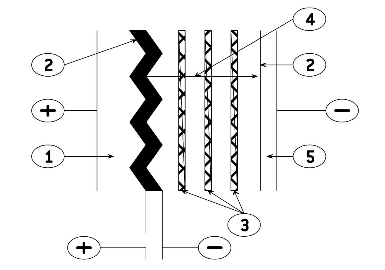
- Anode: aluminum foil
- Dielectric: aluminum oxide
- Papers spacers impregnated with electrolyte
- Ionic conduction assumed by electrolyte
- Cathode: aluminum foil
The positive plate is an etched aluminum foil covered with alumina which is the dielectric of the capacitor.
The negative plate is constituted by a second aluminum foil which serves as a current supply, and by electrolyte-impregnated papers layers.
The metal used for anode is a ≥ 99,98 % grade aluminum.
The dielectric has a thickness of 13 Å / V.
The aluminum used for the cathode is a ≥ 98 % grade aluminum covered with a dielectric layer with a thickness of about 40 Å.
> See our capacitors in catalog

2. Diagram of the equivalent circuit
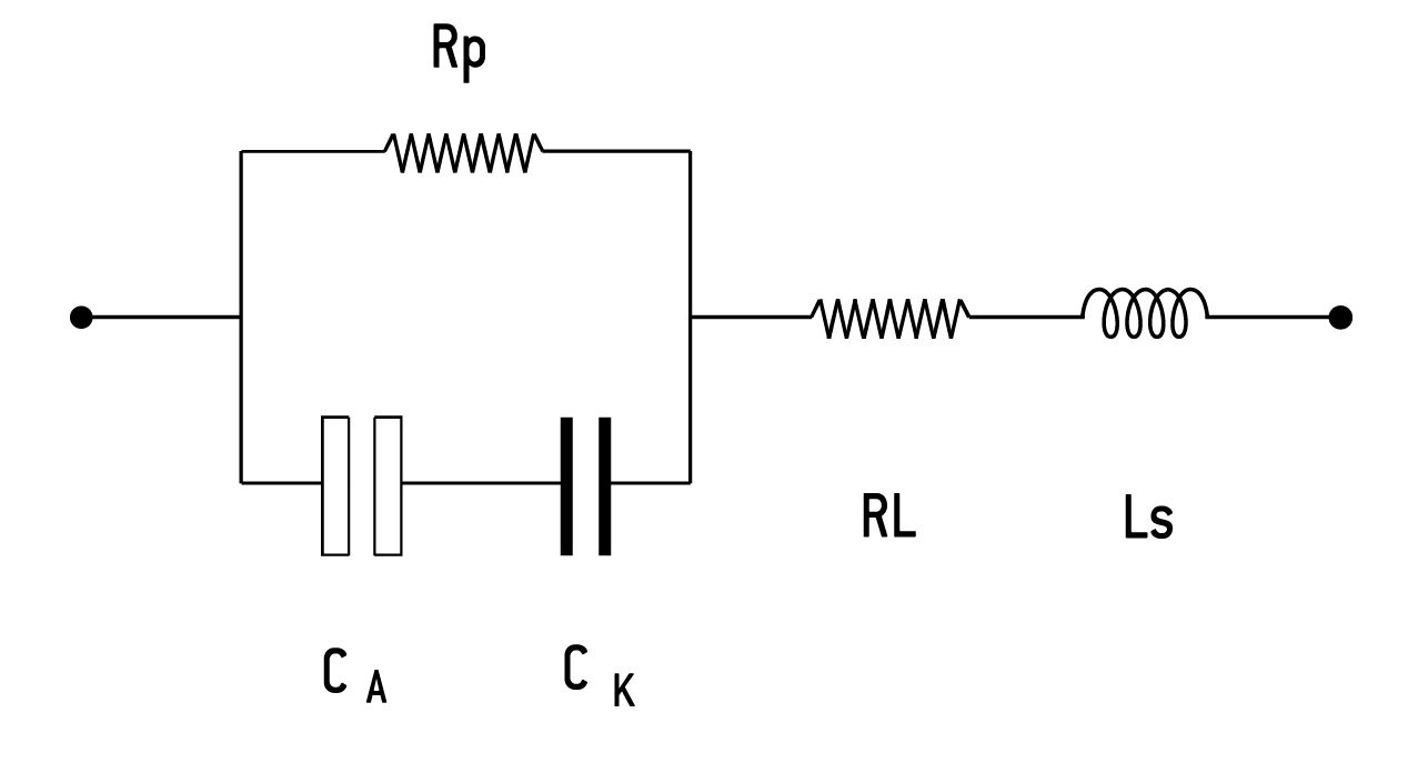
CA = Capacitance of the anode
CK = Capacitance of the cathode
Rp = Parallel resistance due to the aluminum oxide f Ilms.
RL = Series resistance of connections, plates and impregnated spacer.
Ls = Inductance of winding and connections.
A standard simplified diagram is :
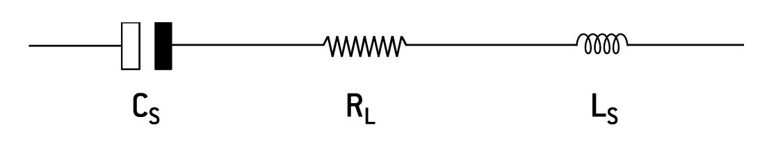
Cs is the series capacitance of both anode and cathode capacitances.
Electrolytic aluminum capacitors are naturally polarized because of the insulating f Ilm on the anode.
Given the very thin aluminum oxide layer, a reversed voltage should not exceed 1.5 V when there is energy supply.
Short duration reverse voltages can be absorbed by special construction, second anode replacing the former cathode.
3. Electrical characteristics
✪ Rated capacitance Cr
The rated capacitance is defined at 100 Hz and at ambient temperature.
✪ Rated voltage Ur
Ur is the maximum DC voltage which may be applied in continuous operation.
When applying a superimposed alternating voltage, the peak value of the resulting waveform should not exceed the rated voltage.
✪ Peak voltage Up
Up is the maximum repetitive voltage which can be applied within short periods.
Defined in CECC 30 300 and IEC 60 384-4:
1000 cycles of 30 s charge followed by a no load period of 5 min. 30 s with upper category temperature.
Up ≤ 1,15 UR (UR ≤ 315 V)
Up ≤ 1,10 UR (UR > 315 V)
✪ Dissipation factor Tan
The dissipation or loss factor is defined by its tangent Tand
✪ Equivalent series resistance ESR
The relation between ESR and dissipation factor Tand.
✪ Impedance Z - Inductance L
The impedance is given by:
Z =g R2 + (Lv –1 )2
Cv
L inductance. Generally L = 5 to 20 nH
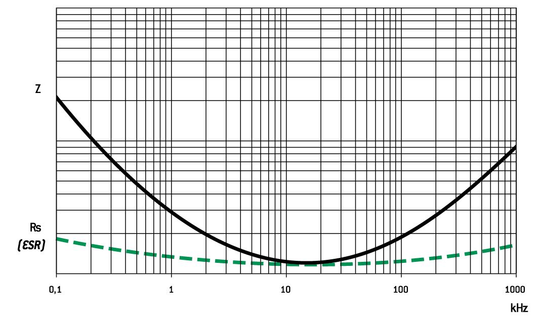
Z and ESR as function of frequency typically follows the chart:
✪ Permissible ripple current (I r.m.s.)
The current is defined at the maximum climatic category and at 100 Hz.
It is the root mean square value r.m.s. The value I0 is the rated value for calculations of expected life up to3 I0.
✪ Leakage current Il
Il is measured at 20°C after a 5 min. polarization under rated voltage.
For CR in μF and UR in V:
Il ≤ 0,01 CR UR or 1 μA*
when CR UR ≤ 1000 μC
Il ≤ 0,006 CR UR + 4 μA
when CR UR > 1000 μC
For UR > 350 VDC it can be specified:
with K = 4, 6 or 8
or
Il ≤ 0,3 (CR UR)0,7 + 4 μA (CECC 30 300)
* Whichever is the greater
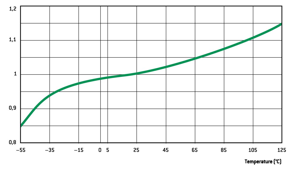
✪ Characteristics
Versus temperature (typical values).
- Capacitance drift
Versus temperature
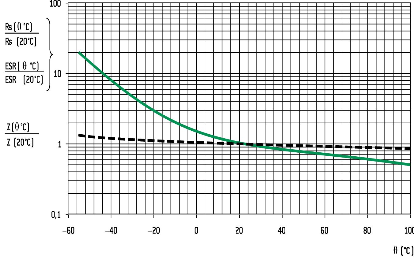
- ESR and Z drifts at 100 Hz
Versus temperature
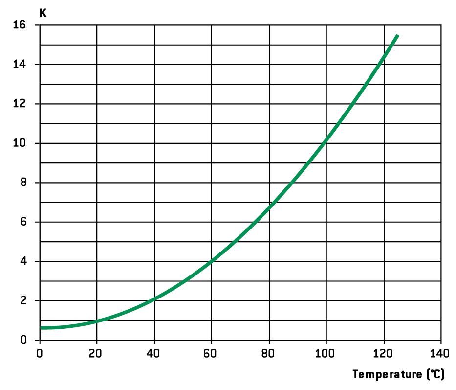
- Leakage current drift
Versus temperature
> See our capacitors in catalog
4. Specification to apply
Electrolytic aluminum capacitors are defined in:
- NF and UTE French national standard
- CECC European specifications
- IEC international specifications
Quality insurance procedures are described in these specifications.
5. Endurance tests / life time
✪ Standard endurance test
at max category temperature:
Standard endurance tests do not exceed 2000 hours at 125°C. However, present EXXELIA technologies concerning liquid electrolytes have led to endurance tests up to 5000 hours at 125°C (PRORELSIC 125 - FELSIC 125 RS) and even 20000 hours at 125°C (PRORELSIC 145 - ALSIC 145).
✪ Performance requirements on standard endurance tests
Permissible capacitance drift ∆C/C (%)
Permissible increase factors on Tand, ESR, Z and Il initial values
(1) Tand or ESR: for initial value, take standard value.
(2) Z: for initial value, take specified value (see data sheet ).
Specific requirements can be taken into consideration with regards to initial values of dissipation factor or equivalent series resistance and impedance.
✪ Failure criteria for electrolytic capacitors
Failure criteria are defined in CECC 30 301
- Non measurable defaults leading to complete failure.
- Measurable defaults leading to adjustment losses of the load circuit (failure due to variations).
- Non measurable defaults
They might be summed up as:
- Open circuit
- Short circuit
- Operation of pressure relief device
- Severely damaged insulation
- Unusable terminations
- Measurable defaults
Variations exceeding the values given below characterize a default.
- Capacitance drift ∆C/C (%): 3 times the limit for standard endurance testing or 50 % (whichever is the smallest).
- Tand or ESR: 3 times standard max initial values.
- Z: 3 times standard max initial values.
- Il: initial limit (under load conditions).
Specific requirements can be taken into consideration with regards to lower drifts.
Influence of main parameter on operational life.
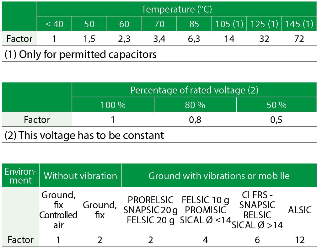
- Temperature
The capacitors operational life is highly dependent upon its internal temperature Ui and therefore upon the ambient temperature and the ripple current.
Knowing ESR and dissipated power values one can figure out, the internal temperature rise and then determine the capacitors expected life.
With present high boiling point electrolytes
Ui max = 125 to 185°C depending on styles.
- Ripple current
The ripple current flowing through the capacitor increase the internal temperature through power dissipation.
Standards define the permissible current at 100 Hz and generally consider a temperature rise of 5 to 10°C of max category temperature.
Current waveforms and frequencies make it difficult to clearly determine the capacitors internal temperature rise, which defines the operationally life.
Experiments confirm following relationship:
Ui = Ua + (Uc - Ua) K
Where:
- Ui = Internal hot spot temperature
- Ua = Ambient temperature
- Uc = Case temperature
- K = Parameter depending upon case diameter and cooling
Ø ≥ 51 k = 2 ± 0,5
Ø < 51 k = 1,5 ± 0,5 (air cooling - 0,2 m/s)
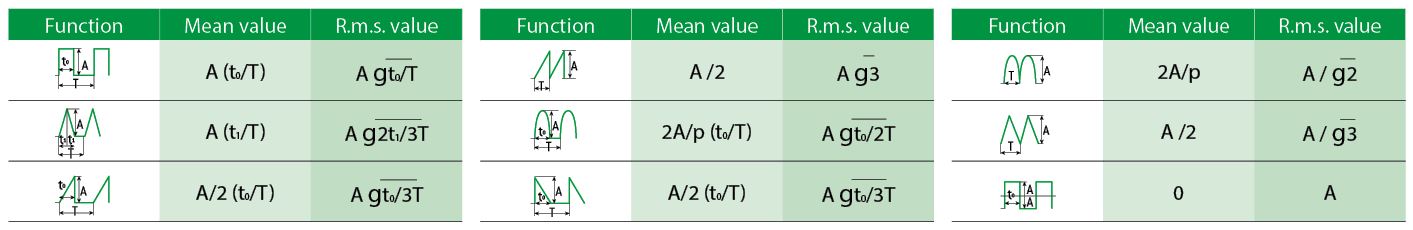
r.m.s. value according to current waveform.
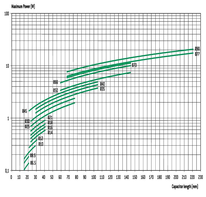
- Dissipated power versus case dimension
For calculations of ripple currents, considering an internal temperature rise of 10°C
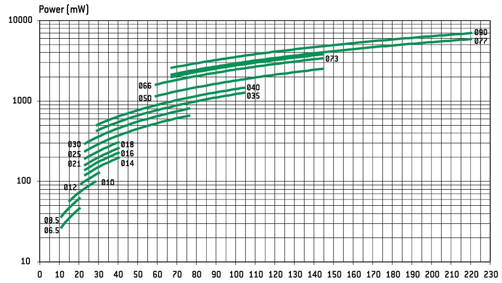
P = ESR.I ²
P = Dissipated power (mW)
(Ui - Ua = 10°C)
ESR: Equivalent series resistance (100 Hz 20°C)
I: Ripple current (r.m.s. value at 100 Hz)
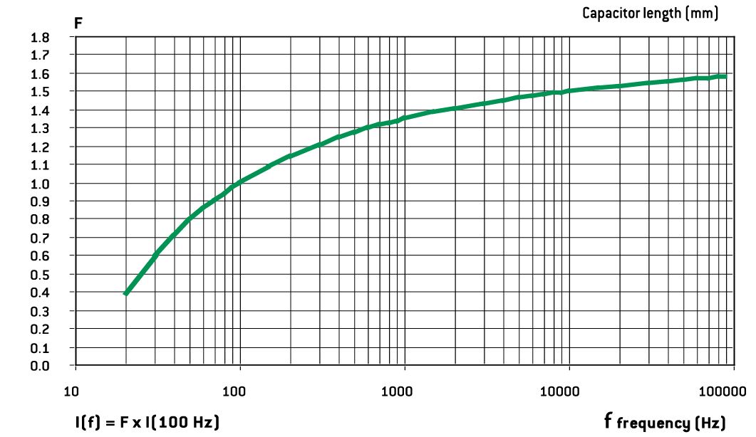
For different frequencies from 100 Hz, I must be multiplied by the factor F, according to above chart.
- Thermal resistance Rth and air cooling
Rth is static thermal resistance (without cooling) between capacitor central hot spot and ambient temperature measured at a distance of one capacitor diameter
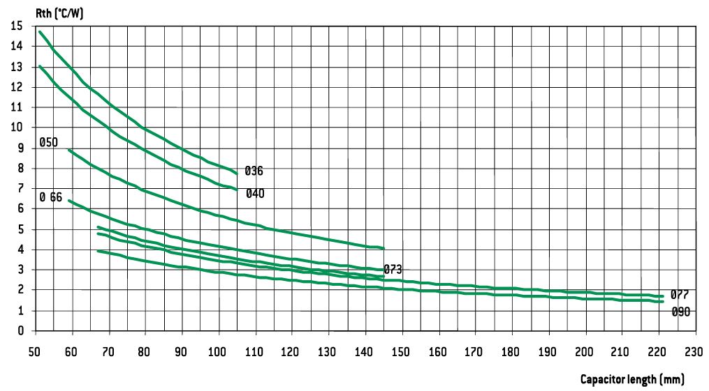
Forced or not cooling air can lead to a significant decrease of these values.
Consequently, r.m.s. ripple current can be increased as a function of air cooling speed:
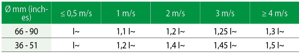
This parameter shall be applied to one capacitor alone.
For capacitors in bank, ambient temperature must be strictly equal around all capacitors.
- Quality guaranty
We guarantee products manufactured during 2 years from the data of shipment against defaults of material and assembly.
This guaranty can be involved by the buyer only if our products are used within normal conditions, always according to the state of the art and taking in account storage conditions.
The equipment design should take into consideration possible failures of our capacitors and related effects in order to avoid them.
Guaranty is not applicable for damages occurred by surge voltage, irregular use, polarity inversion or maintenance default.
Guaranty is exclusively limited to the replacement of individual defective capacitors within the terms of delivery. This rule applied to all cases and particularly to any further consequence of failures.
- Reliability
Failure rate:
FR = Number of components tested x test duration / Number of failures
Failure rate is measured in FIT (failure in time = 10–9 / hour).
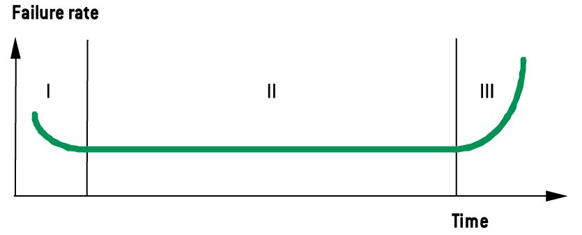
The failure rate is set up during the life time of the capacitor (phase II)
I. Early failure phase (generally excluded during ageing process).
II. Operational life time of the capacitors
III. End of life
Mean time between failures MTBF = 1/FR mesured in years
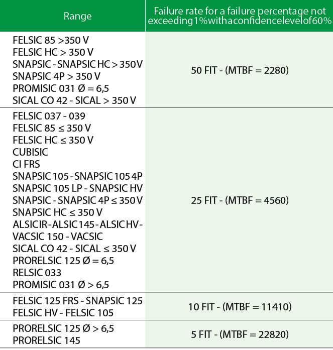
Multiplying factor of FR with voltage and temperature
> See our capacitors in catalog
6. Information on application
✪ Cleaning solvents
Use aliphatic alcohols, such as denatured ethyl alcohol, isopropanol, or butylacetate, or else alkaline d Iluted solutions. Avoid incompatible solvents (halogenous for example).
✪ Shelf life
There is no electrical characteristics variation for long periods of storage except leakage current which can increase.
It is caused by chemical reactions between the dielectric alumina and the electrolyte. These reactions are reversible when switched on. Capacitors can generally be stored at temperature between –5° and +50°C without reforming for the following periods of time:
- For UR ≤ 100 V, storage time: 5 years
- (up to 10 years under specific conditions)
- For 100 V < UR ≤ 360 V storage time: 3 years
- For 360 V < UR < 500 V storage time: 1 year
- For UR ≤ 500 V, storage time: 6 months
Generally when these periods are overstepped, one hour at rated voltage causes the decrease of leakage current under the specified limits. An other way to avoid this leakage current increase problem is to always limit ava Ilable power through capacitor during first seconds or minutes after storage or transport, according to the following chart:
✪ Low pressure resistance
EXXELIA capacitors can be used with ambient low pressure decreasing up to 10 mbar (altitude 28000 m – 92000 feet).
✪ Mounting screw terminals capacitors (FELSIC)
Capacitors may be used vertically (terminals on top) or horizontally. When used horizontally, the following position in relation to the safety vent, is recommended:
Mounting capacitors in series may be used for operating voltage exceeding Ur. See FELSIC in bank.
✪ Mounting solder type capacitors
They may be used in any position. During mounting, avoid applying excessive force to capacitor pins or wires. There is a risk of damaging internal connections.
After soldering and for the same reasons, do not try to move the capacitor's body.
✪ Electrolytes: safety rules
Electrolytes used in EXXELIA capacitors are manufactured by EXXELIA. Main solvents are generally g butyrolactone and ethylene glycol, very stable high boiling point solvents. Ionic conductive salts in electrolyte induce a very weak acidity (pH 5 to 7).
✪ Environment
In aluminium capacitors with liquid electrolyte there is no component showing a pollution risk, in small amounts, of air or water. EXXELIA is always involved in this security field particularly in using chemicals for electrolyte, without well-known risks.
- Dimethylformamide (DMF) dangerous solvent forbidden in several uses is completely excluded by EXXELIA,since 1990.
- There is no halogen compound such as chlorofluorocarbon (CFC or FCKW in german) or polychlorobiphenyl (PCBPyralene) or pentabromodiphenylether or octabromodiphenylether.
There is neither benzene, toluene or phenyl compound nor explosive such as picric acid, nor asbestos in plastic covers. All the capacitors made by EXXELIA since 1991, can be scrapped or used in raw materials recycling processes without special care in compliance with Community rules.
EXXELIA aluminium capacitors with non-solid electrolyte are particularly suitable for different kinds of environment taking in account severity increasing laws.
European directives 2003/11/EC, 2002/96/EC (WEEE) and 2002/95/EC (RoHS) applies to all EXXELIA capacitors including every solder type, manufactured with pure tin coated pins or wires, since at least January 2006.
> See our capacitors in catalog