


Actualités
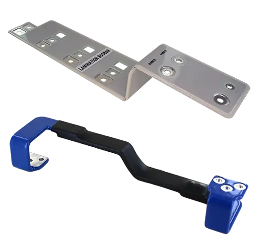
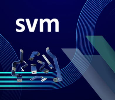
Exxelia SVM: des bus bars haute performance pour l’électronique de puissance
Exxelia SVM Private Limited propose une gamme complète de bus bars conçues pour répondre aux exigences des applications en électronique de puissance. Qu’il s’agisse de bus bars laminées, moulées ou isolées avec des revêtements en résine ou en poudre, chaque solution est pensée pour garantir des performances optimales.
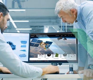
Exxelia dévoile son nouveau site web
Une expérience utilisateur optimisée et des fonctionnalités innovantes
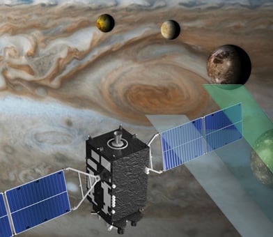
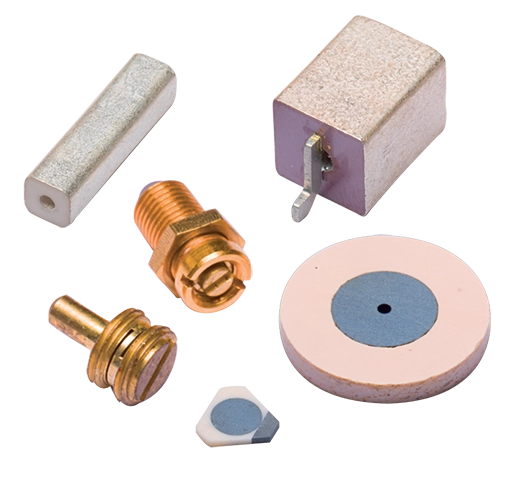
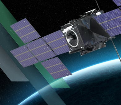
Exxelia Ohmcraft équipe l'Europa Clipper de la NASA avec des résistances personnalisées pour une mission spatiale
Plus de 20 résistances sur-mesure sont essentielles aux instruments scientifiques d'Europa Clipper, indispensables à l'exploration de la lune de Jupiter
Exxelia étend sa présence en Inde grâce à un investissement stratégique dans SVM
Etandant son offre produits magnétiques pour le secteur médical et ajoutant les busbars à son portefeuille de composants passifs pour l'électronique de puissance.

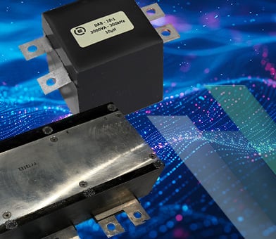
Découvrez notre gamme de condensateurs film Exxelia Alcon
À mesure que le secteur des transports progresse, la demande de composants électroniques fiables et performants devient de plus en plus critique.
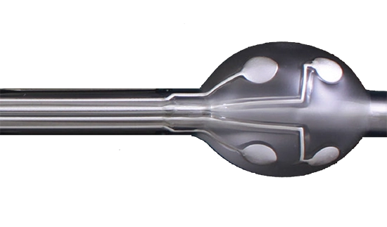
Découvrez la puissance des condensateurs à film MML™
Découvrez comment les condensateurs MML™ d'Exxelia révolutionnent les technologies spatiales avec leur incroyable densité d'énergie de 400 J/dm³. Explorez comment ces condensateurs allègent les charges et garantissent une fiabilité inégalée, ouvrant ainsi de nouvelles voies dans l'exploration spatiale
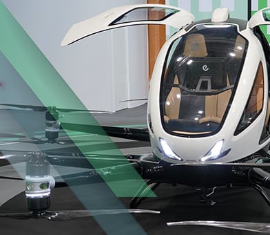
Exxelia équipe les eVTOLs
L'initiative Smart Magnetics d'Exxelia introduit une approche révolutionnaire des convertisseurs électriques, spécialement conçue pour répondre aux exigences des véhicules eVTOL (Electric Vertical Takeoff and Landing).
Exxelia Smart Magnetics : amélioration des convertisseurs de puissance résonants et bidirectionnels de nouvelle génération
Exxelia présente des innovations révolutionnaires dans la technologie magnétique, spécifiquement adaptées aux convertisseurs de puissance bidirectionnels & résonants. Ces avancées devraient redéfinir les normes d'efficacité et de performance dans un spectre d'applications diversifiés.
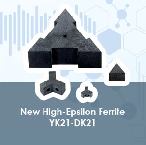
Exxelia présentera ses condensateurs et ses nouvelles ferrites micro-ondes à l'IMS Microwave week 2024
Au stand 2108, Exxelia présentera ses principales gammes de condensateurs RF/Micro-ondes : séries Super HiQ & High-Power High-Q CP/CL.
Exxelia présente ses Innovations au CMSE 2024
Exxelia a le plaisir d'exposer au CMSE 2024 à l'hôtel Four Points by Sheraton, à Los Angeles, du 30 avril au 2 mai 2024. Visitez notre stand B11
100 ans
d'expérience
La plus ancienne entreprise d'Exxelia a été fondée en 1921
3100
employés
NASA
certification
50 ans
D'expérience
Dans le traitement des matériaux et de la méthodologie Micropen
13
sites
répartis dans 5 pays : France, USA, Maroc, Inde et Vietnam