Countering Threats from Transients in Magnetics ; Exxelia to Showcase Innovations at CMSE 2024

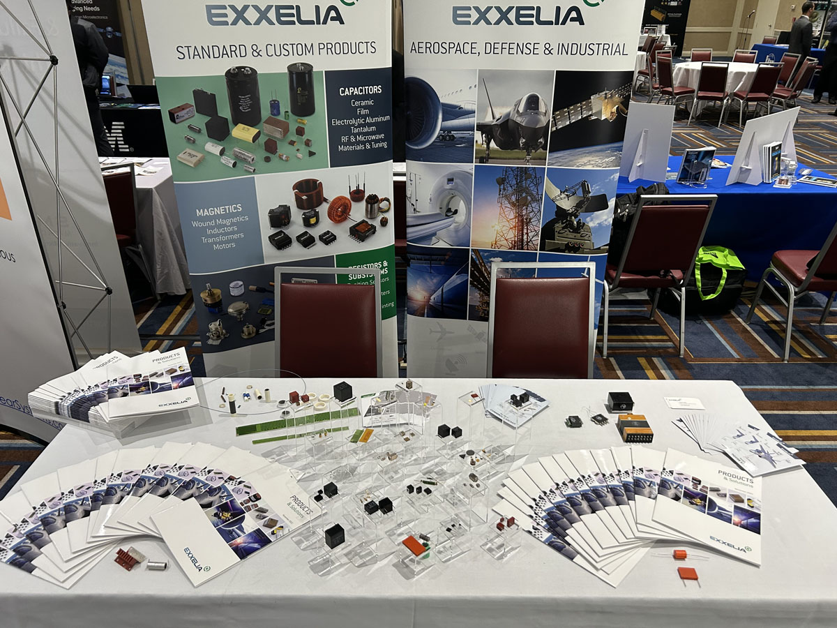
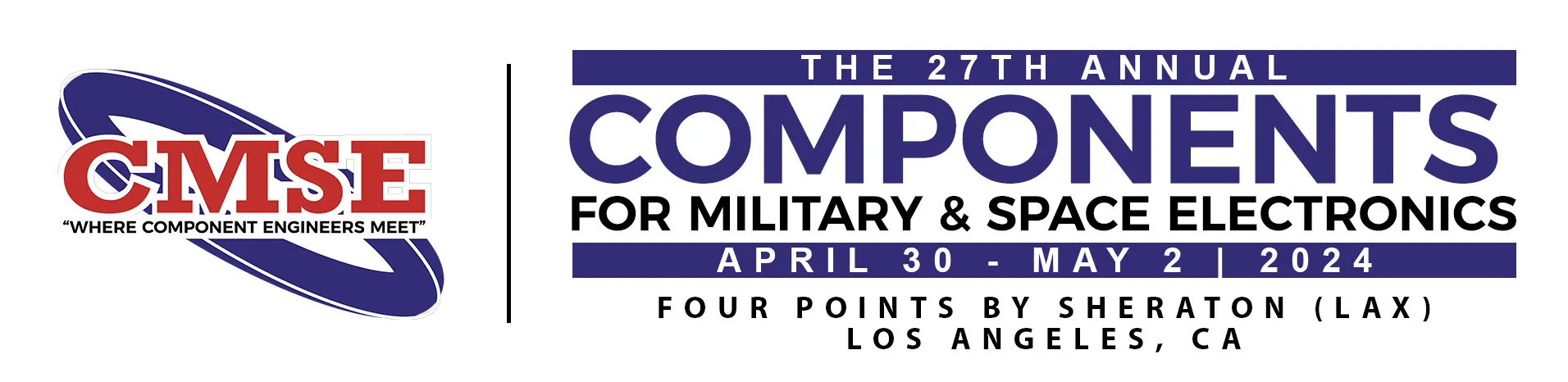
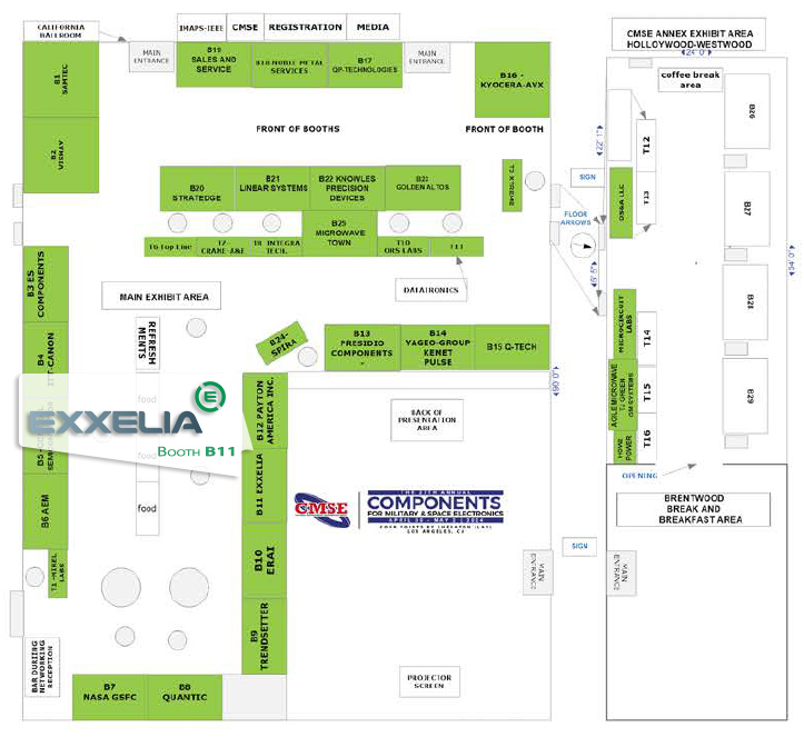
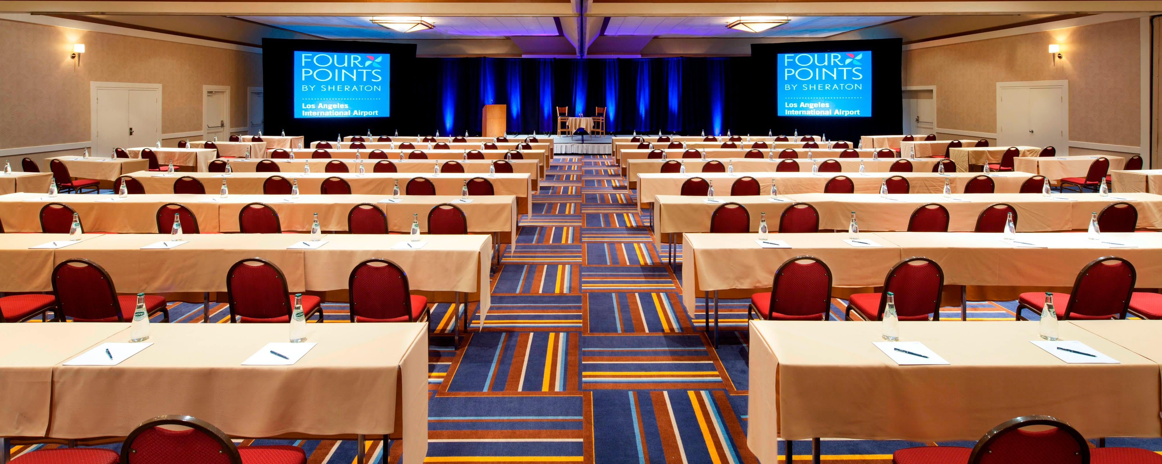
Exxelia is pleased to exhibit at CMSE 2024 in Four Points by Sheraton hotel, in Los Angeles, from April 30 to May 2, 2024. Visit our booth B11


CMSE 2024The event will feature a compelling presentation by Exxelia's own Victor Quinn* on the topic of magnetics. 


CMSE
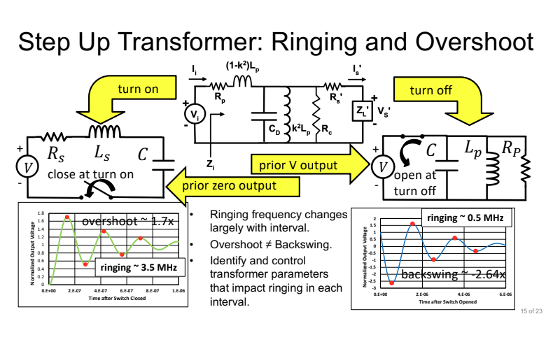
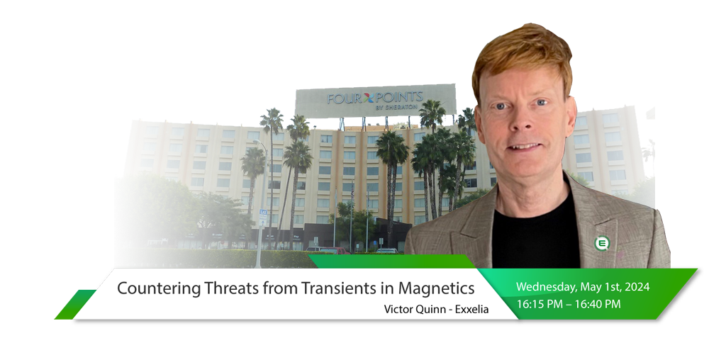
Victor Quinn, a renowned expert in magnetics, will be taking the stage at the CMSE (Component, Materials, and Systems Engineering) conference in Los Angeles to deliver a compelling presentation titled "Countering Threats from Transients in Magnetics." This presentation aims to shed light on the potential risks posed by transient conditions on magnetic components and provide valuable insights into mitigating these risks throughout the product lifecycle.


About the Session:

Victor Quinn's presentation will delve into the nuances of transient-induced failures in magnetic components, offering attendees a comprehensive understanding of the underlying mechanisms at play. By exploring real-world case studies and practical examples, Quinn will highlight the diverse range of transient threats that engineers may encounter in their designs.

The insights shared in Victor Quinn's presentation are expected to resonate with a wide audience, including component engineers, design engineers, project managers, and other magnetics sourcing authorities. 


Why Attend:

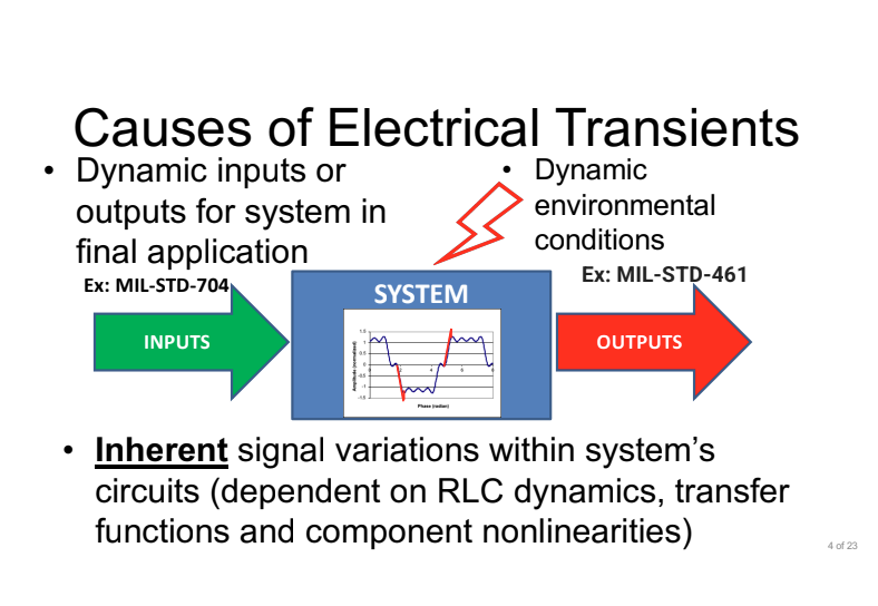
Transient conditions may cause unexpected responses from magnetic components.

These responses may threaten system functions and reliability. Presentation content will help attendees understand potential threats from transients in magnetic components and learn related risk mitigation strategies starting at initial specification phase through qualified production.

The presentation content is expected to benefit component engineers, design engineers, project managers and other magnetics sourcing authorities interested in preventing failures from transient conditions. Exxelia invites all attendees to join this insightful session to explore the fascinating world of magnetics. 

CMSE slide


CMSE slide


Be sure to mark your calendars for Wednesday, May 1st, 2024, at 16:15 PM, and don't miss the chance to be part of this engaging presentation.


Event Details:

The conference will be held in the main conference room, and attendees will also have the opportunity to ask Mr. Quinn questions at the end of his presentation. We hope to see you there.


Title: Countering Threats from Transients in Magnetics

Date: Wednesday, May 1st, 2024

Time: 16:15 AM – 16:40 AM PT


We also invite you to chat with our teams at our booth B11


CMSE 2024


CMSE 2024


* About Victor W. QUINN

  • Victor Quinn Title: Director of Engineering and Technology
  • Affiliation: Exxelia USA
  • Biography of Presenter:

Victor W. Quinn manages Exxelia’s US Magnetics Design Center with responsibilities for research and technology implementation on new products. With degrees in Physics and Electrical Engineering, since 1980 Mr. Quinn has specialized in magnetic component design and development for a wide variety of industrial, aerospace, space and defense applications. He holds a longstanding interest in advancing magnetic components using improved design and empirical test methods and developing novel technologies that increase volumetric efficiency. Mr. Quinn has been granted multiple patents and others pending related to these efforts.


CMSE 2023

Published on 23 Apr 2024 by Stéphane PERES

MIL Spec 39006, Now available in LEVEL R

Exxelia, global manufacturer of complex passive components and subsystems for harsh environments, is expanding its line of MIL-PRF-39006/22 & MIL-PRF-39006/25 tantalum capacitors, with the support of the reliability level R. MIL-PRF-39006 tantalum capacitors equivalent to CLR79 and CLR81 series: this is the new range of gelled tantalum capacitors meeting the standards required by the US Department of Defense in the manufacturing of components (compatibility & reliability).   Exxelia now offers reliability level R, in addition to level M and P for voltage ranges from 6 V to 125 V with capacitance values ranging from 1.7 µF to 1 200 µF. Available in all package sizes (T1 to T4), these fully sealed products are designed to operate at temperatures ranging from -55°C to +125°C and withstand the harshest environmental conditions. Performance highlights over solid tantalum capacitors include higher energy density, higher ripple currents, lower ESR and lower DC leakage current. Engineers with complex design requirements looking for a product that can be easily integrated into projects such as power supplies & converters or filtering units for the aerospace and defense industries will be pleased.  MIL 39006/22 & MIL 39006/25 Level R are now available for order with a lead time of 14 weeks.   "The introduction of these new ranges builds on our decades of experience in supplying high reliability capacitors to the military market and demonstrates Exxelia's ability to meet the most demanding specifications in terms of product development" says Jerome Tabourel, Exxelia's vice president of sales and marketing. "We are proud to be one of the few MIL qualified tantalum capacitor manufacturers, and our flexibility and advantageous lead times will bring new supply opportunities."   TECHNICAL CHARACTERISTICS Capacitance from 1.7 μF to 1,200 μF Voltage from 6 V to 125 V Operating temperature -55°C to +125°C Very good shock and vibration resistance (option H available)   Download the complete datasheet    

High Voltage Resistor Selection Checklist

Introduction to High Voltage Resistor Selection Checklist The resistor is the most common and well-known passive electrical component. A resistor is a device connected into an electrical circuit to introduce a specified resistance. The resistance is measured in Ohms. As stated by Ohms Law (E=IR), the current through the resistor will be directly proportional to the voltage across it and inversely proportional to the resistance. Resistors have numerous characteristics that determine their accuracy during use. The performance indices affect the accuracy to a greater or lesser extent depending on the application. Some of these indices are: Tolerance at DC, Temperature Coefficient of Resistance (TCR), Voltage Coefficient of Resistance (VCR), Noise, Stability with respect to Time and Load, Power Rating, Physical Size, and Mounting Characteristics. Resistor networks typically require temperature and voltage tracking performance. Please refer to the application note: Glossary of Resistor Terminology for an expanded explanation of resistor terminology. Selection Requirements 1. Determine the resistance in ohms and watts. 2. Determine the proper physical case size as controlled by voltage, watts, mounting conditions, and circuit design requirements. 3. Select the resistor that meets your needs for type, termination and mounting. Step 1 : Determine the resistance in ohms and watts. Ohm’s Law: E=IR or I=E/R or R=E/I Ohm’s Law, as shown in the above formula, enables one to define the voltage (E), current (I), or resistance (R) when two of the three terms are known. When current and voltage are unknown they must be measured in the model circuit.   Power Law: W=I2R or W=EI or W=E2 /R Watts (power) can be determined from the above formulas that are derived from Ohm’s Law. R is measured in Ohms, E in volts, I in amperes, and W in watts. Watts must be accurately determined before resistor selection. Simply stated any change in voltage or current produces a much larger change in wattage (heat dissipated by the resistor). The effects of relatively small increases in voltage or current must be determined because the increase in wattage may be significant enough to influence resistor selection. As stated in the above formulas the wattage varies as the square of the current or voltage. Allowances should be made for maximum possible voltage. Step 2 : Determine the proper physical case size as controlled by voltage, watts, mounting conditions, and circuit design requirements. Power Rating and Physical Size: A resistor operated at a constant wattage will reach a steady temperature that is determined largely upon the ratio between the substrate size (surface area) and the wattage dissipated. Temperature stabilizes when the sum of the heat loss rates (by radiation, convection, and conduction) equals heat input rate (wattage). The larger the resistor surface area per watt to be dissipated, the greater the heat loss rate and therefore the lower the temperature rise. Free Air Wattage Rating (Maximum Power Rating) is defined as the wattage rating of resistors as established under specified standard conditions. The absolute temperature rise for a specific resistor is roughly related to the area of its radiating surface. It is also dependent upon a number of other factors such as thermal conductivity, ratio of length to width, heat-sink effects of mounting, and other minor factors. The precise temperature limits corresponding to 100% rated wattage are somewhat arbitrary and serve primarily as design targets. Once a wattage rating has been assigned on the basis of an empirical hot spot limit, the verification of its correctness must be established through long term load life test (see Application Note: Life Test Data – High Voltage Chip Resistors) based on performance and stability standards rather than the measurement of hot spot temperature. Step 3 : Select the resistor that meets your needs for type, termination and mounting. ✔ Resistor Selection: Select the most suitable resistor that meets the requirements of the application. OhmCraft resistors are made to your specification. Refer to the appropriate data sheet to determine part number or call OhmCraft for assistance. ✔ Wattage Rating: To allow for the differences between actual operating conditions and the Free Air Wattage Rating it is a general engineering practice to operate resistors at less than the nominal rating. ✔ Voltage Rating: Determine maximum applied (working) voltage that the resistor will be exposed to and select the appropriate package size. ✔ Pulse Operation: When a resistor is operated in a pulse application, the total power dissipated by the resistor is a function of the pulse’s duty cycle. Typically, one will define the number of joules of energy the resistor must dissipate and choose a resistor accordingly. For additional information refer to our Pulse Resistor white paper or contact OhmCraft. ✔ High Frequency: OhmCraft resistors, due to their design and construction, have very low capacitance and are inherently a non-inductive design. For additional information refer to our High Frequency Attributes Application Note. ✔ Military and Other Specification: The special physical operating and test requirements of the applicable industrial or military specification must be considered. Contact OhmCraft for additional information. Effect of the power ratings on components All the components of an electrical apparatus including resistors, capacitors, rectifiers, and semiconductors have their own limitations as to the maximum temperature at which they can reliably operate. The attained temperature in operation is the sum of the ambient temperature plus the temperature rise due to the heat dissipation in the equipment. Ambient Temperature Derating, below defines the percent of full load that power resistors can dissipate as a function of ambient temperature. Temperature Coefficient of Resistance Temperature Coefficient of Resistance (TCR) is expressed as the change in resistance in ppm (0.0001%) with each degree of change in temperature Celsius (C). MIL STD 202 Method 304 is often referenced as a standard for measuring TCR. This change is not linear with temperature. TCR is typically referenced at +25C and changes as the temperature increases or decreases. It can be either a bell or S shaped curve. It is treated as being linear unless very accurate measurements are required, then a temperature correction chart is used. A resistor with a TCR of 100 ppm will change 0.1% over a 10-degree change and 1% over a 100-degree change. An example of a TCR curve can be found in the application note: Glossary of Resistor Terminology. The following formula expresses the rate of change in resistance value per 1 C in a prescribed temperature range. TCR (ppm/°C) = (R-R0)/R0 X 1/(T-T0) X 106 - R: Measured resistance (Ω) at T °C - R0: Measured resistance (Ω) at T0 °C - T: Measured test temperature °C - T0: Measured test temperature °C In the context of a resistor network, this TCR value is called absolute TCR in that it defines the TCR of a specific resistor element. The term TCR tracking refers to the difference in TCR between each specific resistor in the network. Voltage Coefficient of Resistance The Voltage Coefficient of Resistance is the change in resistance with applied voltage. This is entirely different and in addition to the effects of self-heating when power is applied. A resistor with a VCR of 100 ppm/V will change 0.1% over a 10 Volt change and 1% over a 100 Volt change. VCR becomes very important in high Ohmic value resistor (100M Ω and above) where typical VCRs can be greater than 1000 ppm/V to specify the voltage that will be applied. Failing to do this may result in a resistor that will not meet your specification. The rate of change in resistance value per 1 volt in the prescribed voltage range is expressed by the following formula: VCR (ppm/V) = (R0-R)/ R0 X 1/(V0-V) X 106 - R: Measured resistance (Ω) at base voltage - R0: Measured resistance (Ω) at upper voltage - V: Base voltage - V0: Upper voltage In the context of a resistor network, this VCR value is called the absolute VCR in that it defines the VCR of a specific resistor element. The term VCR tracking refers to the difference in VCR between each specific resistor network. Please refer to the application note: Voltage Ratio Tracking and Voltage Coefficient of Resistance. Summary When specifying a resistor, the following parameters MAY be of interest. Please use this chart to help you define the operating characteristics for your specific application. All of them may not important for your specific application. Also, please do not hesitate to contact Ohmcraft for application help. At Exxelia Ohmcraft, our commitment transcends the creation of resistors. We are dedicated to empowering the visionary innovations that define the future of military technology. Our team is poised to collaborate and customize solutions that perfectly align with the evolving needs of military applications. In a landscape where reliability is non-negotiable and precision is imperative, Exxelia Ohmcraft stands as the beacon of unwavering support, fortifying military operations with resilient, high-performance resistors. Download our White Paper   Exxelia Ohmcraft’s sister division, Exxelia Micropen Medical is at the forefront of medical device product development, providing design engineers with unique insights on conceiving and implementing new designs and features.